4
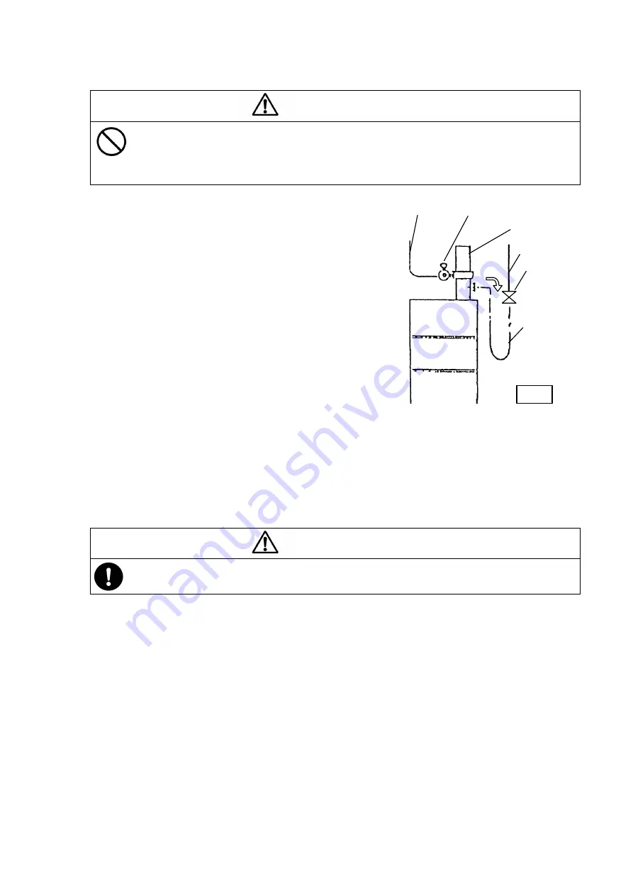
Pump
Piping
Valve
Material
Hose
Air hose Air regulator
3.4 Installing the Pressure Feed Material Hose
For pressure-feeding oil by piping at a long distance, observe the following procedure.
- Do not connect the pump directly to the piping. Otherwise, when the pump is
operated, the piping is damaged, the pump generates large noise, the pump does
not permit changing the drum can, and the pump cannot be serviced. Be sure to
connect a flexible hose between the pump and the piping.
1) Install the hose union and material hose
(separately available) to the material discharge
port (Rc 3/4) of the pump. Tighten the hose
union with a spanner so as not to make
thematerial hose loose. In this case, wind the
seal tape that is available on the market around
the male screw of the hose and then screw it.
2) Install a valve between the end of the hose and
the piping. (Fig. 4)
3) Be sure to install a relief valve so that leak may
not be caused to the piping or damage may not
be given to the hose connecting portion by the
liquid pressure increased by temperature
changes in the piping. The relief valve should
be installed near the pump.
3.5 Air Connection
1)
Install the air regulator (separately available) at the air supply port of the pump. The
dedicated air regulator is available as the standard product. Please use it.
2) Connect the air hose from the compressor to the IN side of the air regulator.
- Be sure install the air regulator at the air supply port for the safe use of the pump.
(The air regulator consists of a reducing valve and a pressure gauge.)
[NOTE]
●
When air is supplied to the air hose, the pump is in operation.
Before connecting the air hose, be sure to turn the knob of the air regulator
counterclockwise to reset the pointer of the pressure gauge to “0”.
●
Using the air regulator permits adjusting the supply air pressure to the pump and
reducing the wasteful motion of the pump, with the result that the operability is improved
and the pump life is extended.
Regarding the method of adjusting the air pressure with the air regulator, the pressure is
increased by turning the knob clockwise (the pointer of the pressure gauge gradually raises
from “0”) and reduced by turning it counterclockwise (the pointer of the pressure gauge
goes back to “0”).
In the normal operating status, the pointer of the pressure gauge should be at 0.3 to 0.5
MPa.
CAUTION
CAUTION
Fig.4
Содержание SH-160A10
Страница 17: ...12 5 5 Parts Disassembly Drawing and Parts List Parts Disassembly Drawing...
Страница 21: ...MEMO...


