


GB-6
For temperature limits for aluminium, cast iron or stainless
steel pumps, refer to the diaphragm material temperature
limits. The air motor is made of aluminium, except for types
NDP-5 and 15 with PPS air motor, and NDP-P20 and P25 with
PPG air motor. For PPS, the material temperature range is
-20 °C to +100 °C. For PPG, the material temperature range is
0 °C to +70 °C.
For products with a plastic compound body material, the maxi-
mum allowed air pressure may be limited by the fluid temperature.
The material temperatures only indicate that the materials
can keep certain strength under certain conditions.
Product application and operation should be decided by
the characteristics of what is being pumped combined with
the temperature, pressure and physical characteristics or
requirements of the application itself.
AMBIENT TEMPERATURE RANGE
Casing pumps and dampeners
0 °C to +70 °C
WARNING
Always use the temperature range suitable
for all materials.
SURFACE TEMPERATURE
For ATEX certified products, the maximum surface temperature
T95 °C has been determined without the presence of a dust layer.
OPERATING AIR
The pump must be operated by compressed air or nitrogen.
WARNING
Use of compressed air other than the
above may cause air pollution, damage to
the pump, or even an explosion.
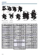
OPERATING PRESSURE RANGE
Series
Pressure Limits (MPa)
DP, NDP, AD
0.2 to 0.7
NDP-H (Plastic Casing)*
0.1 to 0.7
NDP-H (Metal Casing)*
0.1 to 0.85
DP-F (PTFE casing) size 5 to 20
0.2 to 0.5
DP-F (PTFE casing) size 25 to 38
0.2 to 0.7
G
0.2 to 0.7
* PTFE diaphragm must be operated within 0.15 to 0.7 MPa
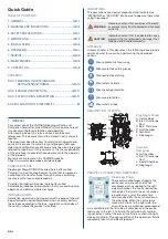
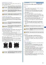
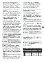
5. INSTALLATION
Make sure that appropriate warnings are displayed on the
pump and surrounding area and all other safeguards are
carried out.
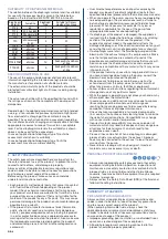
1. Inlet fluid port
6. Air filter regulator
2. Inlet flow valve
7. Pulsation dampener (optional)
3. Drain valve
8. Discharge flow valve
4. Flexible connection
9. Outlet fluid port
5. Air supply
6
6
7
8
4
4
3
2
3
1
9
5
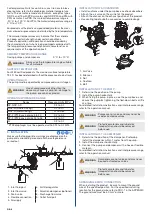
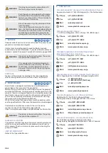
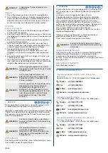
INSTALLATION OF ACCESSORIES
• Install cushions under the pump base as shock absorbers.
• Attach the air valve on the air inlet of the product.
• Attach the silencer on the exhaust position of the product.
• Use sealing tape for both accessories to avoid leakage.
2
1
1
2
3
4
5
1
3
4
5
2
1. Air Valve
2. Silencer
3. Nut
4. Cushion
5. Bolt
INSTALLATION OF THE PUMP
1. Determine the position of the pump.
2. Install the pump horizontally.
3. When fixing the pump in place, use the pump base, and
secure the pump by tightening the tied-down bolts a little
at a time.
For detailed installation instructions and inlet pressure range,
refer to the operation manual.
WARNING
Pumps are not valves and may never be
used or treated as valves.
WARNING
Protective materials and labels for
transportation should be removed
before use.
INSTALLATION OF THE DAMPENER
1. Determine the position of the dampener. Preferably,
install the dampener within 1 meter from the pump.
2. Install the dampener horizontally.
3. Connect the pump and dampener with a hose or flexible
material.
For detailed installation instructions and inlet pressure range,
refer to the operation manual.
WARNING
Dampeners are not valves and may never
be used or treated as valves.
WARNING
Protective materials and labels for
transportation should be removed
before use.
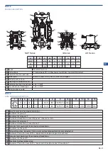
ARRANGING EARTH CONNECTION
When installing the product, be sure to mount the ground
wire at the specified position. For the specified mounting
location for the ground wire, refer to DOC-1 in the APPENDIX.
The ground wire must be 4.0 mm
2
or more.


