HOIST
OPERATION & MAINTENANCE
5
P/N: 11854801 REV. AC
September 2017
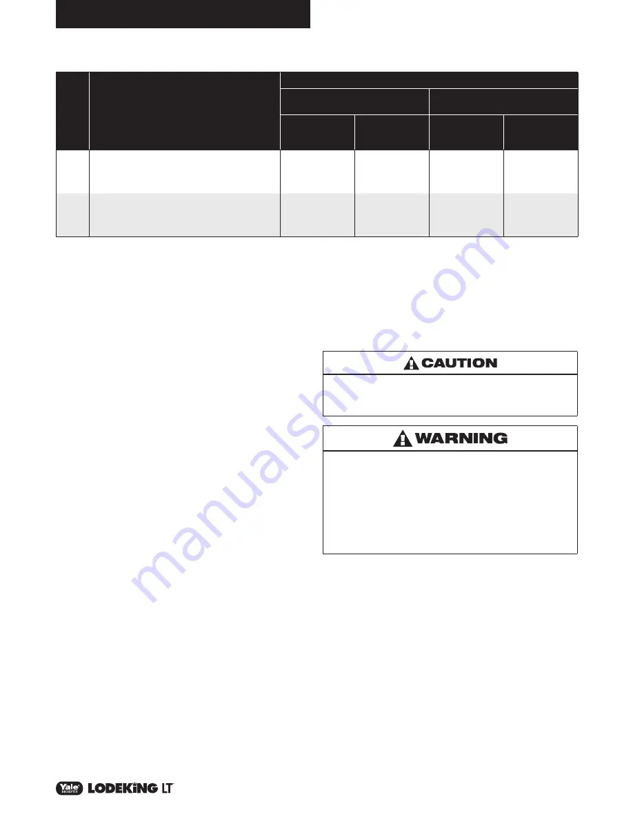
Yale
Hoist
Duty
Class
Typical Areas
of Application
Operational Time Ratings
Uniformly Distributed
Work Periods
Infrequent Work Period
Hoist Running 50% Time
(3)
Max. on Time
Min./Hr.
(4)
Max. No. of
Starts/Hr.
(5)
Max. Time From
Cold Start Min.
(6)
Max. No. of
Starts
H3
General Machine Shop, fabricating, assembly, storage and
warehousing. Where loads and utilization are randomly
distributed, with total running time of equipment not
exceeding 15-25% of the work period.
15
150
30
200
H4
High volume handling in steel warehousing, general
machine shops, fabricating, assembly, mills and foundries.
Total running time does not exceed 35% of work period.
Loads at or near rated capacity frequently handled.
30
300
30
300
YALE HOIST DUTY SERVICE CLASSIFICATIONS
DECK MOUNT INSTALLATION INSTRUCTIONS
1. It is the responsibility of the Crane Builder to ensure that the trolley
system meets all applicable standards and guidelines available from
but not limited to ANSI, HMI and CMAA in terms of load ratings,
duty cycles and factors of safety.
2. CMCO does not participate in or condone field modification or
product usage in a manner inconsistent with the design function. It
is the responsibility of the crane builder to ensure compliance with
CMCO specifications and guidelines for mounting and operation of
this equipment
3. Refer to drawing C45570401 LodeKing Deck Mount Clearance
Diagram and the specific order clearance diagram for details such
as frame loading, mounting pad dimensional specifications and
overall unit envelope dimensions
4. Weld on shear blocks shall be attached by a qualified welder using
a weld that has been sized properly for the application, and welded
per AWS D14 Specifications.
5. The weld on shear blocks and the angle iron feet shall not be
subject to loading in the vertical direction. The shear block systems
is designed to resist hoist motion in the horizontal direction only.
Hoist frame loading in areas not approved by CMCO is prohibited.
6. Welding the shear blocks while still attached to the hoist frame is
not recommended due to the possibility of stray voltage from the
welding operation damaging the electrical components present on
the hoist
7. The trolley mounting surfaces shall be flat and in the same plane
within 0.015”
8. Hoist frame loading in areas not approved by CMCO is prohibited
9. Deck mount angles to shear block mounting bolts shall be installed
with Loctite, and torqued to 300-325 ft-lbs. Bolts shall be c
hecked
at least yearly for signs of loosening.
INSTALLATION INSTRUCTIONS
Before the unit is shipped from the factory it is rigidly tested and
carefully adjusted for proper operation. However, the following points
must be checked to insure correct installation and avoid damage to
the hoist.
1.
ROPE AND DRUM:
Check the hoist rope for any signs of
damage and make sure it lies properly in the grooves of
the drum and sheaves. Make sure the rope is well lubricated.
2.
LUBRICATION:
Every attempt has been made to ship the
hoist with the proper amount of lubricating oil in the gearcase.
Before placing the unit-in operation, check the level on the sight
gauge. The oil should be level with the level hole. If more oil is
needed, consult the Lubrication Chart. Also make sure breather
plug hole is cleared.
3.
CURRENT SUPPLY:
make sure the electric current supply
corresponds with the rating listed on the hoist nameplate.
Make sure duty cycle capabilities of hoist are fully understood
by all operators.
4.
ELECTRICAL CONNECTIONS:
Open the control box and
check all the electrical connections ~ to be sure they are tight
and that none of the hardware vibrated loose during shipment.
5.
PUSH BUTTON CONTROL:
THE HOIST MUST BE GROUNDED. TO DO THIS CONNECT
A SUITABLE GROUND WIRE IN THE SUPPLY WIRING TO A
SOLID GROUND AND TO THE SUPPLY GROUNDING LUG
SUPPLIED IN THE HOIST CONTROL PANEL.
TO INSURE CORRECT OPERATION OF THE SAFETY LIMIT
STOPS, IT IS VERY IMPORTANT THAT THE HOOK TRAVEL
IS IN THE HOISTING DIRECTION WHEN THE ‘UP’ BUTTON
IS PRESSED. IF IT IS NOT, INTERCHANGE ANY TWO OF THE
MOTOR LEADS IN THE MOTOR CONDUIT BOX. DO NOT
CHANGE PUSHBUTTON WIRING. INTERCHANGING WIRES
ON THE LINE SIDE OF THE INVERTER WILL NOT AFFECT
SHAFT ROTATION DIRECTION. IF THE HOIST IS OPERATED
WITH INCORRECT POWER CONNECTIONS, THE SAFETY
LIMIT STOPS WILL BE INEFFECTIVE AND SERIOUS DAMAGE
AND DANGEROUS ACCIDENTS MAY RESULT.
Содержание Lodeking LT Series
Страница 30: ...30 P N 11854801 REV AC September 2017 HOIST MOTION 200 230 575V 15 20HP 200 575V 25HP WEG MOTORS ...
Страница 50: ...NOTES ...
Страница 51: ...NOTES ...


