TROLLEY
OPERATION & MAINTENANCE
29
P/N: 11854801 REV. AC
September 2017
MOTOR BRAKES
Standard motor brakes are DC rectified solenoid activated, spring
set disc type brakes. Brake is intended to be used strictly as a
holding brake and does NOT have any torque adjustment for
decelerating and stopping the crane. Deceleration and stopping is
to be provided by the variable frequency (inverter) motor control.
BRAKE AIR GAP INSPECTION
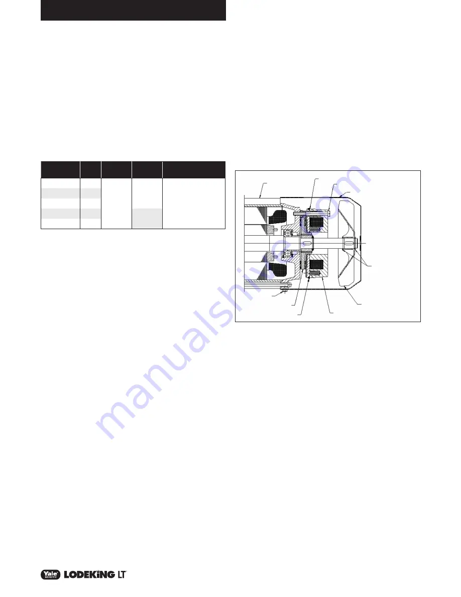
To inspect brake air gap refer to figure 6:
1. Disconnect and lock out power supply
2. Remove brake cover
3. Carefully roll the o-ring back towards the magnet body
exposing the air gap between the armature plate and magnet.
Use feeler gauge and measure the gap between the armature
plate and magnet. If gap exceeds maximum allowed, replace
the brake.
Motor
Horsepower
KW
Normal Air
Gap
Maximum
Air Gap
Brake Mounting Bolt
Torque
0.75
.55
0.2 mm
(.008 in.)
0.3mm
(.012 in.)
3 Nm
(2.2 ft. lbs.)
1.0
.75
1.5
1.2
2.0
1.5
0.4 mm
(.016 in.)
3.0
2.2
4. Roll o-ring back into place and re-install brake cover.
5. Turn power back on to crane and test brakes for proper
operation.
BRAKE RECTIFIER REMOVAL
AND REPLACEMENT
Rectifier is located inside the motor conduit box cover. To replace
follow these steps:
1. Disconnect and lock out power supply.
2. Unplug motor leads and open conduit box.
3. Remove rectifier and unplug wires.
4. Plug wires into replacement rectifier.
a. Connect brake leads to DC side of rectifier, terminals marked
“+” & “–”.
b. Connect leads from the plug to the AC side, two terminals
marked “~”.
5. Re-assemble in reverse order disassembly.
6. Turn power onto crane and test for proper operation.
BRAKE REMOVAL AND REPLACEMENT
If brake air gap exceeds the maximum allowed, or is not functioning
properly, the brake may need to be replaced. Follow these
instructions.
1. Turn power off to crane and lock out
2. Unplug motor leads, open motor conduit box and disconnect
brake leads from rectifier
3. Remove brake cover
4. Remove retaining ring and fan (if applicable).
5. Remove (3) mounting bolts holding brake magnet body in
place. Pull brake leads from motor, remove magnet, brake coil
and rotor.
6. Re-assemble in reverse order, and tighten mounting bolts to
specified torque.
7. Turn power back on to crane and test brakes for proper
operation.
Motor End Bell
Shroud Bolt
Brake Disc
O-Ring
Magnet Body
Retaining Rings
(where applicable)
Shroud
Brake Mounting Bolts
Air Gap
Plastic Fan
(where applicable)
Figure 6: Motor Brake
ELECTRICAL
1.
Gearmotors
a. The gearmotors are inverter duty. If gearmotor requires
any service or repairs, other than what is described in this
manual, the complete gearmotor must be replaced.
b. For hoist and trolley motors, consult the hoist and trolley
literature.
2.
Control Panel
a. All connections should be checked frequently for tightness.
3.
Hoist and Trolley
Panel, brakes, limit switches, etc. Consult hoist and trolley
literature for maintenance and spare parts information.
Содержание Lodeking LT Series
Страница 30: ...30 P N 11854801 REV AC September 2017 HOIST MOTION 200 230 575V 15 20HP 200 575V 25HP WEG MOTORS ...
Страница 50: ...NOTES ...
Страница 51: ...NOTES ...


