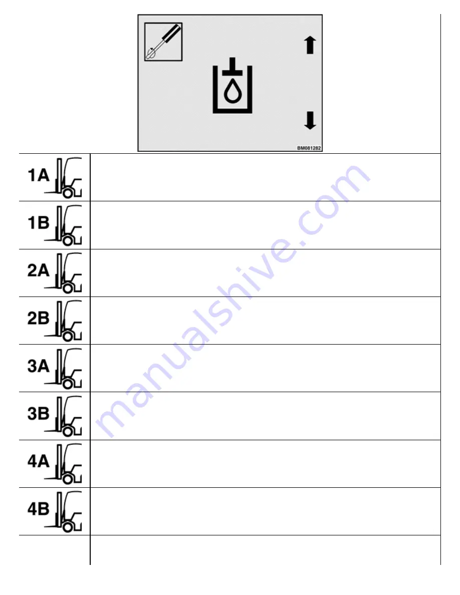
Valve Threshold Function 1 "A" Direction Prompt Icon
Valve Threshold Function 1 "B" Direction Prompt Icon
Valve Threshold Function 2 "A" Direction Prompt Icon
Valve Threshold Function 2 "B" Direction Prompt Icon
Valve Threshold Function 3 "A" Direction Prompt Icon
Valve Threshold Function 3 "B" Direction Prompt Icon
Valve Threshold Function 4 "A" Direction Prompt Icon
Valve Threshold Function 4 "B" Direction Prompt Icon
This icon points to the * key and is used for valve calibration in this submenu.
Содержание ERC40VH
Страница 8: ...Figure 3 Supervisor Flowchart Sheet 1 of 4...
Страница 9: ...Figure 3 Supervisor Flowchart Sheet 2 of 4...
Страница 10: ...Figure 3 Supervisor Flowchart Sheet 3 of 4...
Страница 11: ...Figure 3 Supervisor Flowchart Sheet 4 of 4 Table 1 Supervisor Menu Flowchart A B C D E F G H...
Страница 21: ...Hydraulics Icon Alert Screens Cycle the Key Secure Battery Release Park Brake...
Страница 22: ...Operator Out of Seat Release Pedal Release Hydraulic Input Traction Switch...
Страница 23: ...Hydraulic Switch Temperature Too High Lift Limit Charge Battery...
Страница 26: ...Display Title Screen Status Title Screen Truck Setup Title Screen...
Страница 105: ...Figure 71 Steering Wheel Number of Turns Valid Entry...


