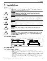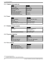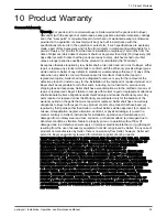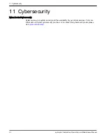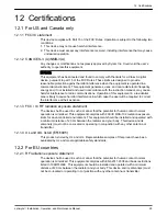
5.3.2 Flat plate mounting
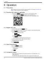
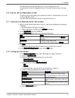
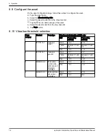
• The flat plate mounting can be used where the mounting surface is non-ferrous.
• The sensor must be mounted near bearings or other potential sources of vibration and
increase in temperature.
• For true close-coupled pumps, the mounting location must be near the motor bearings.
• There must be sufficient space to remove the sensor and mounting plate safely without
harm or injury.
5.3.3 Sensor
• The infrared sensor window must be in direct line of sight with the surface of the asset
being measured.
• Avoid installation of the sensor on any sheet metal enclosures surrounding the asset.
• The sensor must be mounted near bearings or other potential sources of vibration and
increase in temperature.
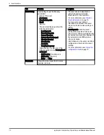
• Follow the correct sensor orientation guidelines.
For more information, see
on page 13
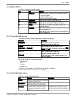
5.4 Install the standard magnetic mounting
1. Install the standard magnetic mounting on one of the following surfaces of the asset:
– Flat and dry
– Curved: The minimum diameter must be 180 mm (7 in).
2. Check that the mounting is stable on the asset surface.
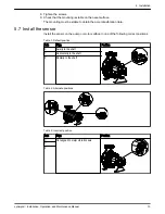
5.5 Prepare the flat plate mounting
1. On the asset, locate the surface to install the mounting.
2. Put the mounting plate on the location.
3. Use the outer most holes in the mounting plate to mark the position of holes on the
surface of the asset.
4. Drill the holes at the marked position.
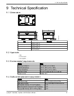
– The flat plate mounting requires a size M6 or 1/4 in -20 tap.
– The diameter of the hole must be 5 mm or 13/64 in.
– The depth of hole must be 13 mm or 1/2 in.
– The distance between the holes must be 105 mm (4.1 in).
5. Deburr the holes.
6. Use a M6x1 (1/4 in - 20) threading to tap the holes.
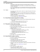
5.6 Install the flat plate mounting
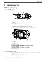
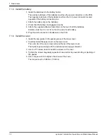
1. Remove the magnetic mounting feet from the sensor.
2. Put the sensor face down.
The infrared sensor window must not be blocked.
3. Put the flat plate mounting on the sensor.
The countersunk holes must face away from the sensor.
4. Align the four screw holes of the flat plate mounting and four blind holes of the sensor
housing.
For more information, see
on page 13.
5. Install the screws.
6. Use a torque wrench to tighten the screws.
The torque must be 0.88 Nm (7.8 lbf.in).
7. Install the flat plate mounting and sensor on the pump.
5 Installation
12
optimyze
™
Installation, Operation, and Maintenance Manual
Содержание optimyze
Страница 1: ...Installation Operation and Maintenance Manual P2007013_1 0 optimyze...
Страница 2: ......
Страница 30: ......
Страница 31: ......

