


1. Peel off the outer sheath at the end of the cable.
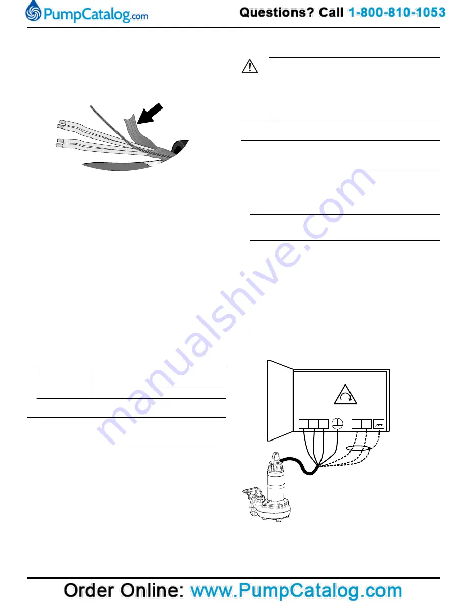
2. Prepare the control element:
a) Peel the insulation sheath or plastic jacket.
b) Peel the aluminum and textile layers.
The aluminum foil is a conductive screen. Do not peel more than
necessary, and remove the peeled foil.
WS004313F
Screened SUBCAB
T
1
T
2
T
3
T
4
Figure 4: Aluminum foil on the control element.
c) Put a white shrink hose over the drain wire.
d) Twist T1+T2 and T3+T4.
e) Put a shrink hose over the control element.
Make sure that the conductive aluminum foil and drain wire are
covered.
3. Prepare the ground (earth) core of the SUBCAB
™
cable:
a) Peel the yellow-green insulation from the ground (earth) core.
b) Check that the ground (earth) core is at least 10% longer than
the phase cores in the cabinet.
c) If applicable, put a cable lug on the ground core.
4. Prepare the ground (earth) core of the screened SUBCAB
™
cable:
a) Untwist the screens around the power cores.
b) Twist all power core screens together to create a ground (earth)
core.
c) Put a yellow-green shrink hose over the ground (earth) core.
Leave a short piece uncovered.
d) Check that the connected ground (earth) core has sufficient
slack. The core must stay connected even if the power cores are
pulled loose.
5. Prepare the power cores:
a) Remove the aluminum foil around each power core.
b) Peel the insulation from each power core.
6. Prepare the ends of the ground (earth) core, the power cores, and
the drain wire:
Connection type Action
Screw
Fit cable lugs to the ends.
Terminal block
Fit end sleeves or leave the ends as they are.
4.2.4 Connect the motor cable to the pump
NOTICE:
Leakage into the electrical parts can cause damaged equipment or a
blown fuse. Keep the end of the motor cable dry at all times.
1. Remove the entry gland screw from the stator housing.
2. Remove the stator housing.
This provides access to the terminal block/closed end splices.
3. Check the data plate to see which connections are required for the
power supply.
4. Arrange the connections on the terminal block/closed end splices
in accordance with the required power supply.
5. Connect the mains leads (L1, L2, L3, and ground (earth) ) according
to applicable cable chart.
The ground (earth) lead must be 50 mm (2.0 in.) longer than the
phase conductors in the junction box of the unit.
6. Make sure that the pump is correctly connected to ground (earth).
7. Make sure that any thermal contacts incorporated in the pump are
properly connected to the terminal block/closed end splices.
8. Install the entry gland screw on the stator housing.
4.2.5 Connect the motor cable to the starter and
monitoring equipment
DANGER: Explosion/Fire Hazard
Special rules apply to installations in explosive or flammable
atmospheres. Do not install the product or any auxiliary
equipment in an explosive zone unless it is rated explosion-
proof or intrinsically-safe. If the product is rated explosion-
proof or intrinsically-safe, then see the specific explosion-
proof information in the safety chapter before taking any fur-
ther actions.
NOTICE:
Thermal contacts are incorporated in the pump.
NOTICE:
Thermal contacts must never be exposed to voltages higher than
250 V, breaking current maximum 5 A.
1. If thermal contacts are included in the pump installation, then con-
nect the T1 and T2 control conductors to the MiniCAS II monitoring
equipment.
If the temperature of the pumped liquid is above 40°C (104°F), then
do not connect the T1 and T2 leads to thermal contacts.
NOTICE:
The thermal contacts are incorporated in the stator. Connect them
to 24 V over separate fuses to protect other automatic equipment.
2. Connect the mains leads (L1, L2, L3, and ground (earth)) to the start-
er equipment.
For information about the phase sequence and the color codes of
the leads, see Cable charts.
3. Check the functionality of the monitoring equipment:
a) Check that the signals and the tripping function work correctly.
b) Check that the relays, lamps, fuses, and connections are intact.
Replace any defective equipment.
4.2.6 Cable charts
Description
This topic contains general connection information. It also provides ca-
ble charts that show connection alternatives for use with different ca-
bles and power supply.
WS000509E
L2
L3
L1
L1
L3
L2
T1 T2
Figure 5: Phase sequence
10
Содержание GOULDS 2GFK2412H
Страница 1: ...Installation Operation and Maintenance Manual 90002801_3 0 1310...
Страница 2: ......
Страница 23: ......


