Xtrails ADPRO iFT Скачать руководство пользователя страница 29

ADPRO

iFT Series Hardware Installation Manual

27817_05

29

5

Motherboards

5.1

Overview

The iFT Series operates with a MiTAC PH10LU motherboard.

MiTAC PH10LU motherboard

5.2

BIOS Settings

Choose 

Main 

System Time 

to set the system time.

Choose 

Main 

System Date 

to set the system date.

Choose 

Chipset 

PCH-IO Configuration 

Front Panel Audio 

and select 

Legacy Front Panel

.

Choose 

Boot 

CSM parameters 

Launch PXE OPROM policy 

and select 

Legacy only

.

Choose 

Save & Exit 

Exit and Reset 

and press Enter.

Leave all other parameters to the default settings.

5.3

Connectors

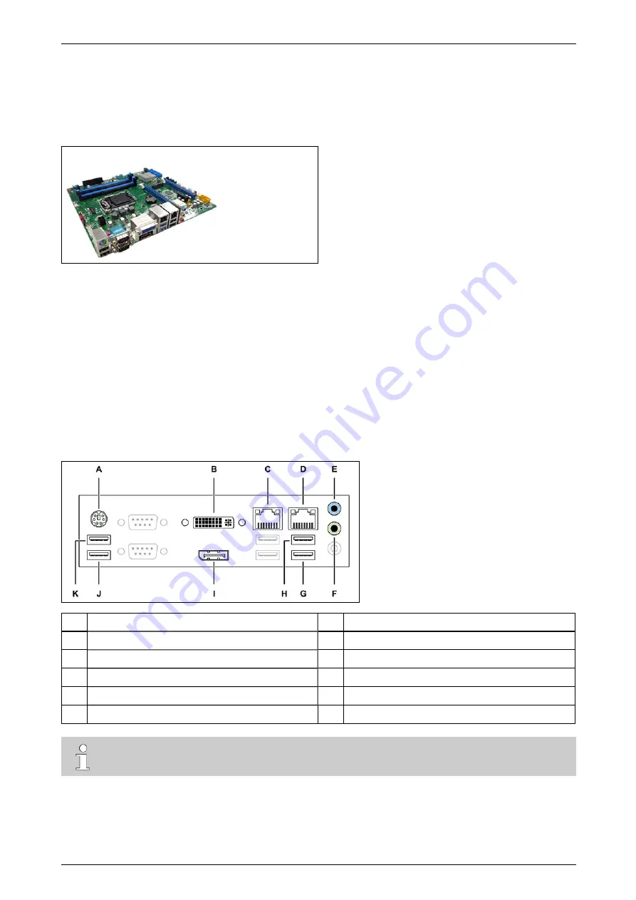
The image below indicates the available motherboard connectors at the rear of the device.

A

PS/2: keyboard or mouse

G

/dev/ttyU4 (USB)

B

DVI-I: monitor

H

/dev/ttyU3 (USB)

C

eth0: network for XO device

I

DisplayPort: monitor

D

eth1: network for IP cameras

J

/dev/ttyU1 (USB): modem

E

Audio line in

K

/dev/ttyU2 (USB)

F

Audio line out


Note

The XO device does not support the USB 3 ports on the PH10LU motherboard.

Содержание ADPRO iFT

Страница 1: ...ADPRO iFT Series Hardware Installation Manual March 2017 Doc 27817_05 Firmware version XO 4 00 ...

Страница 2: ......

Страница 3: ... use the products strictly in accordance with the User Manual and product documents available from Xtralis Xtralis is not liable to you or any other person for incidental indirect or consequential loss expense or damages of any kind including without limitation loss of business loss of profits or loss of data arising out of your use of the products Without limiting this general disclaimer the foll...

Страница 4: ...ed out wheeled bin means that within the European Union the product must be taken to separate collection at the product end of life This applies to the device but also to any accessories marked with this symbol Do not dispose of these products as unsorted municipal waste If you need more information on the collection reuse and recycling systems please contact your local waste administration You ca...

Страница 5: ...urth Disk in an iFT E Device 22 3 9 RAID 1 Support 26 3 9 1 About RAID 1 26 3 9 2 Activating RAID 1 26 3 9 3 Retrieving RAID 1 Information 27 4 Front LED Indicators 28 5 Motherboards 29 5 1 Overview 29 5 2 BIOS Settings 29 5 3 Connectors 29 5 4 Replacing the Motherboard 30 5 5 Replacing the Motherboard Battery 30 6 Connecting IP Cameras 31 7 Main I O Card 33 7 1 Features 33 7 2 Overview of Inputs ...

Страница 6: ...o Serial Port RS 485 Converter 54 13 7 Connection via the IFM 485 ST Interface Module 54 13 8 Connection via IP Modules PRO E IPM 54 13 8 1 Summary 54 13 8 2 Setting up the IP Modules 55 13 8 3 Connecting the IP Modules to the PIR Detectors 59 14 Power Consumption 60 15 Retrieving the IP Address 61 16 Diagnostics 62 16 1 Log Files and Reports 62 16 2 Retrieving Log Files 62 16 3 Retrieving Reports...

Страница 7: ...river Command inputs 8 inputs on the box balanced 20 inputs balanced via XO I O Interface USB module Via Ethernet I O module with PoE up to 128 go no go Relay outputs 4 outputs on the box SPDT 8 outputs SPDT via XO I O Interface USB module Via Ethernet I O module with PoE up to 128 SPDT Web server XO client integrated web client application ActiveX Ethernet 2 x 100 1000BASE T autodetection full du...

Страница 8: ...t requires min 2 equal HDDs Warranty 2 years Dimensions W x H x D 441 x 88 x 305 mm 17 36 x 3 46 x 12 00 Analytics Basic motion detection VMD camera sabotage detection Up to 16 iFT or 32 iFT E analytics channels for IntrusionTrace LoiterTrace and SmokeTrace Mobile apps iTrace iPIR iCommission iRespond Ordering information Please contact your local Xtralis ADPRO provider for detailed product inform...

Страница 9: ...e maximum 16 analytic channels with 16 32 16 video channels For optimal performance disable the monitor output when using more than 16 IP channels on an iFT Note The most recent iFT models come with a system license that supports 32 IP channels The system license in older systems supports only 16 IP channels You can upgrade your system license free of charge using Xchange For instructions see Fiel...

Страница 10: ...every major software upgrade Upgrade information may consist of system requirements special upgrade instructions etc Before installing new software make sure that you read and understand the upgrade information first Always follow the instructions in the upgrade documentation If in any doubt do not install the new software You can find upgrade instructions on the Xtralis Security Support site www ...

Страница 11: ...pace based on the past recordings For details see the XO Client Software User Manual 21796 The iFT Series devices are standard delivered without or with 1 hard disk inside You can install l In the iFT model o maximum 2 hard disks in models without extra mounting holes in the rear o maximum 3 hard disks in models with two extra mounting holes in the rear The labels on the suitable iFT devices indic...

Страница 12: ...a disk from another device and you need to recover the recordings that are on the used disk follow the instructions in the Tech Tip Recovering Recordings from Used HDDs 29160 3 4 Retrieving Hard Disk Information You can retrieve hard disk information and identify possibly faulty hard disks using the Telnet ta smart command or using the XO client software 3 4 1 Using the ta smart Command SMART stan...

Страница 13: ...ient Software To obtain to obtain the SMART information for all hard disks in the XO device in the XO client choose System Maintenance Harddisks The Smart column shows the operational status of the hard disks the Temp column indicates the temperature 3 5 Installing the First Hard Disk Note If you need to install 2 hard disks follow the instructions in Installing a Second Hard Disk on page 16 inste...

Страница 14: ...the hard disk to the bottom of the casing Caution If you tilt the casing rest it carefully on the sides but not on the back You may damage the connectors if you do Depending on the available holes in the casing and the hard disk the following options exist o Casing with 6 screw holes in the bottom use the first 4 holes or the outer 4 holes with 4 disk screws 17434080 o Old casing with 4 screw hole...

Страница 15: ...he SATA cable 16520877 Caution Do not bend the SATA cables too sharply to prevent cable damage 5 If the SATA cables do not have a locking mechanism use tie wraps to secure the cables on the disk s in the following way 6 If there are unused cables left bundle them with tie wraps 7 Place the top cover back fix it with 2 screws at the front 4 at the top and 3 at the back ...

Страница 16: ...rd disk Part Amount reference number Disk screws 8 x 17434080 SATA cable 1 x 16520877 iFT E HDD bracket 1 x 17011890 iFT E HDD bracket L shaped 1 1 x 17011895 Caution l Before installing hard disks stop the device Switch it off and unplug the power cord l Take all necessary precautions to prevent static discharges that may damage the device use an anti static wristband an anti static mat l The pro...

Страница 17: ...17011890 and 17011895 and 8 screws 17434080 as shown below Make sure that the mounting screw holes on hard disk 1 are on the outside A bracket 17011890 B L shaped bracket 17011895 4 Fix hard disk 1 to the bottom of the casing For instructions depending on the model and hard disk capacity see Installing the First Hard Disk step 2 on page 14 5 Connect hard disk 1 to the power supply and to the SATA1...

Страница 18: ...77 Caution Do not bend the SATA cables too sharply to prevent cable damage The table below lists the correct devices and SATA connectors Device SATA connector DOM SATA0 HDD1 SATA1 HDD2 SATA2 7 If the SATA cables do not have a locking mechanism use tie wraps to secure the cables on the disk s in the following way 8 If there are unused cables left bundle them with tie wraps ...

Страница 19: ... installed hard disk s in the list and press Enter 14 Choose Format and use selected disks using the tab key The system formats the selected hard disks 15 When formatting is finished choose Main Menu and then choose Reboot The device now restarts After restarting the installed hard disks are ready for use 3 7 Installing a Third Disk in an iFT Device Material required for the third hard disk Part A...

Страница 20: ...ll a used hard disk while keeping the recordings on it follow the instructions in the Tech Tip Recovering Recordings from Used HDDs 29160 To install a third hard disk in an iFT device proceed as follows 1 Stop the device switch off the power supply and then remove the top cover unscrew 2 screws at the front 4 at the top and 3 at the back 2 Fix the third disk on the mounting bracket 17011920 using ...

Страница 21: ...e power SATA cable from the second disk and plug in the Y cable 16520795 This provides power supply connections for all three disks 6 Connect disk 2 to one end of the Y cable and disk 3 to the other end 7 Connect hard disk 3 to the SATA3 connector on the motherboard with the SATA cable 16520877 Caution Do not bend the SATA cables too sharply to prevent cable damage The table below lists the correc...

Страница 22: ...l then stop at the boot window and this gives you time to select and open the XO Installer menu 13 Choose Update current system Manage recording disks 14 Select the newly installed hard disk s in the list and press Enter 15 Choose Format and use selected disks using the tab key The system formats the selected hard disks 16 When formatting is finished choose Main Menu and then choose Reboot The dev...

Страница 23: ...ch Tip Recovering Recordings from Used HDDs 29160 To install a third and fourth hard disk in an iFT E device proceed as follows 1 Stop the device switch off the power supply and then remove the top cover unscrew 2 screws at the front 4 at the top and 3 at the back 2 Fix disks 3 and 4 on the mounting bracket 17011920 using 8 disk screws 17434080 Disk 3 Disk 3 and 4 3 Before mounting the bracket wit...

Страница 24: ...o the power supply and to the SATA3 connector on the motherboard with the SATA cable 16520877 6 Connect hard disk 4 to the power supply and to the SATA4 connector on the motherboard with the SATA cable 16520877 Caution Do not bend the SATA cables too sharply to prevent cable damage ...

Страница 25: ...it for the boot window to appear 11 Select XO Installer and press Enter Note The boot window only appears for a few seconds then the device continues booting To make sure that you do not miss it press the arrow keys on the keyboard repeatedly while the device is booting The device will then stop at the boot window and this gives you time to select and open the XO Installer menu 12 Choose Update cu...

Страница 26: ...imum 2 hard disks The size of the RAID 1 recording combination is the smaller of the 2 disks installed in your device For example if you have a 1 TB disk and a 2 TB disk the RAID 1 recording disk has a 1 TB capacity Caution When you apply RAID 1 the system formats the selected disks and erases the data on the disks You will lose all the data on the disks Back up your recordings first To activate R...

Страница 27: ... You can retrieve RAID 1 information using the Telnet ta hd raid command or using the XO client software To check if disks are in RAID 1 mode in the XO client software proceed as follows 1 Launch the XO client software 2 Choose System Maintenance Harddisks The following screen appears The MountPoints pane displays the mount points writing disks The Type column indicates whether the mount point is ...

Страница 28: ...ically blinks goes out briefly This is normal behaviour Yellow LED Indicates a fault If the yellow LED lights up check the status of your device For more information see the XO Client Software User Manual 21796 Blue LED Indicates storage media activity Caution When the 3 LEDs are flashing simultaneously the system is servicing the recording disks upgrading formatting In that case do not turn off p...

Страница 29: ...Boot CSM parameters Launch PXE OPROM policy and select Legacy only Choose Save Exit Exit and Reset and press Enter Leave all other parameters to the default settings 5 3 Connectors The image below indicates the available motherboard connectors at the rear of the device A PS 2 keyboard or mouse G dev ttyU4 USB B DVI I monitor H dev ttyU3 USB C eth0 network for XO device I DisplayPort monitor D eth1...

Страница 30: ...vice back to your supplier Remember that the system licenses is linked to the motherboard If you replace the motherboard the system may not recognise the system license and will not be functional 5 5 Replacing the Motherboard Battery It may be necessary to replace the motherboard battery after some time For further instructions see the technical documentation of the motherboard ...

Страница 31: ...et connector eth0 on the motherboard provides the physical interface for this network l The network for the IP cameras The secondary Ethernet connector eth1 on the motherboard provides the physical interface for this network Note It is not possible to have overlapping IP address ranges in eth0 and eth1 these must be separate With software version XO 4 and above the system will check and issue a wa...

Страница 32: ...ic routes to extend the eth1 camera network to these other network segments For the configuration of the static routes see the XO Client Software User Manual 21796 The MiTAC PH10LU motherboard has two LAN connectors on board therefore you do not need a separate Ethernet card to connect to the IP camera network Just connect the IP camera network to the eth1 port using an Ethernet cable You must set...

Страница 33: ...on instructions in the document Main I O and Extension I O Cards Next Generation 27820 7 2 Overview of Inputs and Outputs IN1 8 are voltage free contact inputs OUT1 4 are voltage free relay contact outputs 7 3 Input Circuits Below are the NEOL SEOL and DEOL configurations for the inputs For correct operation you also have to indicate the used input circuit configuration in the XO client software F...

Страница 34: ...r may cause injuries Wiring to Dinkle and Phoenix connectors is identical except that the position of tabs and holes is swapped The picture in the procedure below shows a Phoenix connector To connect inputs and outputs proceed as follows 1 Push the slotted tab firmly inwards with the screwdriver 2 Insert the stripped wire 6 7 mm into the corresponding round hole as deeply as possible 3 Release the...

Страница 35: ...ADPRO iFT Series Hardware Installation Manual 27817_05 35 7 6 Configuring the MIO Card To configure the inputs and outputs or to update the MIO card firmware see the XO Client Software User Manual 21796 ...

Страница 36: ...t use the double module You have to map the MIO and EIO cards in the modules to the correct USB ports ttyUx device nodes using the hardware configuration tool If not the XO device will not discover the cards and you will not be able to use the inputs outputs For detailed information see the XO I O Interface USB Module Technical Manual 32688 Note Although it is technically possible to disable an ex...

Страница 37: ... the day The following window appears 5 In the Validity box enter the time in minutes that the PIN has to remain valid The maximum time is 1440 minutes 24 h 6 Click Create A new PIN appears under Current pin of the day The counter in the Remaining Validity min box displays for how long in minutes the new code is still valid 7 Write down the code including the dashes or keep the window open and mov...

Страница 38: ...ort number For example with the default IP address and control port http 10 0 0 10 2000 login The following screen appears 9 Type the username 15 and password default is 666777 for the Technician user and click Login The following screen appears Note If the Login window appears again check in the XO client software if the Technician user is enabled 10 In the Pin of the day box type the code that y...

Страница 39: ... window appears again you have entered an invalid PIN code The Usb ports list shows the currently configured nodes ttyU6 is the first MIO card ttyU5 is the first EIO card Note that ttyU5 will always appear in the list even if there is no physical EIO card present in the XO device You can now connect the XO I O Interface USB module and map it ...

Страница 40: ...connect the XO I O Interface USB module to the XO device using the provided USB cable insert one end into the module and the other end into a free USB port on the XO device 2 In the hardware configuration tool click Refresh The MIO and EIO card in the module will now appear in the list with the Device Node column empty 3 The first row is the EIO card set the Device Node to ttyU7 ...

Страница 41: ...pply message appears 7 Wait for the message to disappear 8 Click Logout 9 Restart the XO device 10 Open the XO client and check if the module is visible in the I O window choose System Connections I O You will see a second line indicating 2 I O card ext You can now use the MIO EIO cards in the module in the same way as the MIO EIO Next Generation cards The LEDs on the XO I O Interface USB module f...

Страница 42: ...odules you can obtain a total of 128 extra inputs and 128 extra outputs Caution Before plugging or unplugging any extension units switch off the power to the base unit Plugging or unplugging extension units with power on may result in permanent and irreparable damage to the main and or extension units For detailed installation instructions see the ADPRO Ethernet I O Datasheet 20148 Base unit Exten...

Страница 43: ...r to connect a VGA monitor Note For a video monitor you can use an external VGA to PAL NTSC converter To set up live viewing on the monitor see the XO Client Software User Manual 21796 Note l For the iFT model with 32 IP video channels for optimal performance disable the monitor output if you are using more than 16 IP channels on your iFT device This restriction does not apply to the iFT E model l...

Страница 44: ...S 232 converter This USB to RS 232 converter needs a specific FTDI chip The Stollman TA USBA is the only ISDN modem with USB interface that you can use without a converter l 3G 4G modem the XO device supports only the Sierra Wireless Airlink Raven XE modem Xtralis does not guarantee that any other 3G 4G modem will work properly Connect the modem to USB input 1 dev ttyU1 Restart the XO client softw...

Страница 45: ... Talkback to the site works via the Live Video window in the XO client software You select a camera and then use the microphone typically connected to the client PC to talk to the site via the speaker that is associated with that camera If you need only one speaker on your site you have the following options l Connect an amplified loudspeaker to the audio out plug of the motherboard green 3 5 mm j...

Страница 46: ... E Usage is similar to IP cameras with audio out capabilities For details see Using the Axis IP Horn Speaker on page 49 You use the XO client software to assign the different speakers to the cameras For each camera you can choose l One output on a VM22 output switcher l One or more outputs on IP cameras 12 2 2 Setup for VM22A Note The VM22A audio switcher is only compatible with built in MIO cards...

Страница 47: ...a typical setup that allows talkback on the monitored site it provides 20 audio outputs loudspeakers via two VM22A units in cascade A headset connected to the client PC serves as the audio input microphone For more information see the VM22A Audio Switcher Installation and User Manual ...

Страница 48: ...8 DATA 33 GND For more information see the VM22E Technical Manual 29541 12 2 4 Troubleshooting Talkback If talkback does not work check the following l In the XO client software check the access rights of the user Audio talk must be allowed l Routers may block UDP packets In the audio setup in the XO client specify TCP or configure the router to allow UDP packets l Use the PC headphones plug inste...

Страница 49: ...rophone that you can use for audio in You manage the horn speaker on the XO device as if it were an IP camera with audio in and audio out capabilities l You connect the horn speaker to the IP camera network and enable it in the XO client as an IP camera it occupies one IP channel As there is no video from the speaker horn the system will display a speaker icon in the live recorded video windows l ...

Страница 50: ...S 485 bus However you can combine an RS 485 bus and IP modules to connect more PIR detectors to the XO device The maximum number of PIR detectors on an XO device is 34 requires minimum firmware version XOa 3 02 0001 You can connect a PIR detector to only one XO device Note You need a PIR HLI application license to enable the PIR detectors Use Xchange to install the license on the XO device For mor...

Страница 51: ...was default If you experience any problems when connecting devices to the MIO card check the RS 485 PTZ jumper setting Change it if necessary Connect the wires as shown below Some PIR models have separate 0V terminals for data and power on other models there is only one common 0V terminal Make sure to bridge the following connections l TX with RX l TX with RX The PIR detectors are powered locally ...

Страница 52: ...nces and cable lengths further below you can determine which PIR detectors you connect to which channel If necessary you can connect up to 4 distribution units in cascade In that case you connect only one of the 4 distribution units directly to the XO device Keep the following in mind l Before connecting multiple PIR detectors to the same channel you have to assign a unique address to each PIR det...

Страница 53: ... The maximum length of the USB cable between the XO device and the distribution unit is 1 m Four wires connect the PIR detector to the distribution unit power supply and communication The maximum distance between distribution unit and PIR detector is 200 m If the distance is longer than 200 m then the PIR detector needs a separate local power supply ...

Страница 54: ...The IFM 485 ST is an interface module which allows to conveniently connect the RS 485 bus of the PIR detector to the dev ttyU2 USB port of your XO device For detailed installation instructions see the ADPRO IFM 485 ST Legal Disclaimer Intended Use of Product 27178 and the ADPRO PRO E PIR System Setup Manual 26571 13 8 Connection via IP Modules PRO E IPM 13 8 1 Summary IP modules allow you to conne...

Страница 55: ... must set up the serial ports of the IP modules To set up the IP modules proceed as follows 1 Connect the IP modules to the network and make sure that your PC is in the same network 2 Download and install the Lantronix DeviceInstaller program available from www lantronix com products deviceinstaller 3 Launch DeviceInstaller It automatically starts searching for the IP modules xPico devices on the ...

Страница 56: ...s 7 Click Network and provide the correct network settings The example screen above shows the settings for an IP module with IP address 192 168 10 192 Xtralis recommends to use IP addresses in the same range as the local network of the XO device eth0 not in eth1 which is the range of the IP camera network 8 Click OK to save the settings Next you will set up the serial port communication ...

Страница 57: ... the parameters as shown in the screen below Make sure that the Port Settings are as follows Item Description Protocol RS485 2 wire Flow control None Baud rate 9600 Data Bits 8 Parity Event Stop Bits 1 10 Click OK to save the settings Next you will set up the module to use UDP communication ...

Страница 58: ...ick Connection and set the parameters as shown in the screen below Make sure to set the following parameters correctly Item Description Protocol UDP Datagram Type 01 Local Port 5555 12 Click OK to save the settings Next you will apply all the settings to the module ...

Страница 59: ...u can connect the IP modules to the PIR detectors 13 8 3 Connecting the IP Modules to the PIR Detectors For details on connecting the IP modules to the PIR detectors see the document ADPRO PRO E IPM Legal Disclaimer Intended Use of Product 27556 Take into account that the wire colours may be different A Blue Red B Black Orange Brown Yellow GND Red Green After connecting the IP Modules to the PIR d...

Страница 60: ...ximum values Motherboard 13 W Processor 65 W PH10LU with Core i7 4770 S microprocessor 2 Seagate SV35 hard disks 20 W MIO card 1 W TOTAL on secondary circuit 100 W on primary circuit total power consumption divided by 0 78 this is the efficiency of the power supply 128 W 0 56 A 230 VAC Note Measurement on an iFT E device with PH10LU motherboard and i7 microprocessor produced the following results ...

Страница 61: ...creen and a keyboard to the XO device 2 If the monitor displays the video matrix press Ctrl Alt F1 The XO welcome screen appears ADPRO XO 04 00 0007 Ip 10 0 0 10 Subnet 255 255 255 0 Gateway 10 0 0 1 Port HTTP 80 Port CTRL 2000 Port RTSP 554 The XO welcome screen displays the following information o XO device server software version o IP address subnet mask and gateway o HTTP control and RTSP port...

Страница 62: ...nical issues 16 2 Retrieving Log Files The XO device can output its internal trace buffer to hard disk to allow logging for longer periods without losing the data You need to enable logging first To enable logging and retrieve log files proceed as follows 1 Type the device s IP address in the address bar of your internet browser and add log php to the address For example http 10 0 0 10 log php The...

Страница 63: ...e log files appear on the web page in the Log list 3 To retrieve a log file click the link on the web page Depending on your system settings the system will open the file in the browser or will ask to download the file 4 If you have downloaded the file double click it to open it If the following message appears choose Select a program from a list of installed programs and then set Notepad as defau...

Страница 64: ...address of the XO device in the address bar of the browser and add report php to the IP address Example http 10 0 0 10 report php The Server Report contains the following information General Memory usage Time zone Processes Uptime Performance Vmstat I O stat PID stat MP stat Network Interfaces available Interfaces enabled Routes Listen ports Netstat all DEV stats Sockstat ARP cache ...

Страница 65: ...Hardware Installation Manual 27817_05 65 Filesystem Mounts S M A R T Fsck Open files Free disk space Hardware CPU Memory Mainboard PCI Udev database Server Server version Server process memory usage Files Active config ...

Страница 66: ... to the internal logging the core dump and the network trace log php Here you can download the log files see Retrieving Log Files on page 62 report php Here you can consult essential information on the configuration see Retrieving Reports on page 64 core php Here you can download the core dump crash info and watch dump hang info when you encounter these specific problems The Xtralis Support Divisi...

Страница 67: ... device requires almost no maintenance Keep the device dust free Make sure to clean the ventilation grids at the front and back to assure proper airflow in the device Caution Do NOT clean the device with water or any corrosive products Use only dust cloths and wipes to clean the outside ...

Страница 68: ...can easily reinstall your application licenses via Xchange synchronise For instructions see the Xchange Tool User Manual 27816 To perform a full reset using the ImageFlash tool you need the following l the ImageFlash tool l the iFT image file to flash on the DOM l a SATA to USB cable You can find the tool and image file on the Xtralis Security Support site www xtralissecurity com Caution If you pe...

Страница 69: ...e that connects the DOM to the motherboard 13 Unplug the DOM s power cable 14 Insert the SATA to USB cable into the DOM and plug the other end into your PC Note If you are using a new unused DOM you must format it first When you connect the DOM to your PC the system will display a message asking to format the DOM click Yes or OK to format the DOM 15 On your PC double click the FastTrace2ImageFlash...

Страница 70: ...icense error via the event message 0013 SYST SYSTEM LICENSE ERROR and via a popup window at each connection with the XO client You have to restore the system license immediately to have access to full functionality You can restore your system license via the Transfer function in the XO client In some cases you can also try to restore the system license using Xchange For details see the Xchange Too...

Страница 71: ...l 20 for future use l 21 2 x 500 GB l 22 2 x 1 TB l 23 2 x 2 TB l 24 not used l 25 2 x 4 TB l 26 2 x 6 TB l 27 2 x 8 TB l l 29 2 x X TB l 40 for future use l 41 4 x 500 GB l 42 4 x 1 TB l 43 4 x 2 TB l 44 not used l 45 4 x 4 TB l 46 4 x 6 TB l 47 4 x 8 TB l l 49 4 x X TB 00 Transmission only 1 TB X is to be defined in the future 1 1 1 built in MIO card D Special options l 0 no special options l 2 ...

Страница 72: ...d range of iFT Series configurations suitable for a wide variety of security system requirements For an overview of the available configurations and for advice on selecting the one that best suits your needs please contact your Xtralis Sales Representative 20 2 Declaration of Conformity ...

Страница 73: ...ort DTC down the coax DTE data terminal equipment DVD digital video disk DVI I Digital Visual Interface digital and analogue EIO Extension I O EMS Event Management System eth Ethernet interface FACP Fire Alarm and Control Panel fps frames per second ft foot feet FTDI Future Technology Devices International FTP file transfer protocol GB gigabyte GDI Graphics Device Interface GHz gigahertz GND groun...

Страница 74: ...eries device RTP real time transport protocol RTSP real time streaming protocol SATA serial ATA SDK software development kit SEOL single end of line SIF source input format SIM subscriber identity module SMART Self Monitoring Analysis and Reporting Technology SMTP Simple Mail Transfer Protocol SP Service Pack SPDT single pole double throw SPK speaker SVGA Super Video Graphics Array SXGA Super Exte...

Страница 75: ......

Страница 76: ...ddle East 962 6 588 5622 Asia 86 21 5240 0077 Australia and New Zealand 61 3 9936 7000 A Disclaimer about this document statements about Intellectual Property Copyrights and Liability as well as a General Warning are available in an earlier section of this document Document No 27817_05 P N 19532170 ...

Отзывы: