XtendLan XL-GRT402S Скачать руководство пользователя страница 41

XtendLan G.SHDSL.bis Router XL-GRT402S, XL-GRT404S, User Manual 

a. Transport Type; select a transport type from the drop-down list, depending on 

whether you are adding a trigger for a TCP or a UDP application.  

b. Port Number Start; type the start of the trigger port range that the primary session 

uses.  

c. Port Number End; type the end of the trigger port range that the primary session 
uses.  
d. Allow Multiple Hosts; select allow if you want a secondary session to be initiated 

to/from different remote hosts. Select block if you want a secondary session to be 
initiated only to/from the same remote host.  

e. Max Activity Interval; type the maximum interval time (in milliseconds) between 

the use of secondary port sessions.  

f. Enable Session Chaining; select Allow or Block depending on whether you want to 

allow multi-level TCP session chaining.   

g. Enable UDP Session Chaining; select Allow or Block depending on whether you 

want to allow multi-level UDP and TCP session chaining. You must set Enable 
Session Chaining to Allow if you want this to work.  

h. Binary Address Replacement; select Allow or Block depending on whether you 

want to use binary address replacement on an existing trigger.  

i. Address Translation Type; specify what type of address replacement is set on a 

trigger. You must set Binary Address Replacement to Allow if you want this to 
work.  

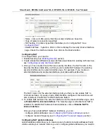
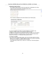
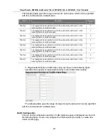
3. Once you have configured the trigger, click on 

Apply

. The Firewall Trigger 

Configuration page is displayed, containing details of the trigger that you have just 
configured.  

4. Each trigger displayed in the Firewall Trigger Configuration page has a Delete 

hyperlink assigned to it. To delete a trigger, click on this link, then at the confirmation 
page, click on the Delete button.  

The Firewall Trigger Configuration page is displayed and details of the deleted trigger 
have been removed. There are two hyperlinks on the page:  

a. To add a new trigger, click on 

New Trigger

.  

b. To display the Security Interface Configuration page, click on 

Return to Interface 

List

.  

 
Configuring Intrusion Detection Settings 


Intrusion Detection settings allow you to protect your network from intrusions such as 
denial of service (DOS) attacks, port scanning and web spoofing. This section 
assumes that you have followed the instructions in 

Enabling Security 

Section

 and 

Enabling Firewall and/or Intrusion Detection 

Section

.  


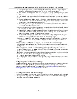
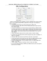
To configure Intrusion Detection settings: 


1. 

Go to the 

Policies, Triggers and Intrusion Detection 

section of the 

Security Interface 

Configuration 

page. Click on 

Configure Intrusion Detection. 

The 

Firewall Configure 

Intrusion Detection 

page is displayed:  

-41- 

Содержание XL-GRT402S

Страница 1: ...G SHDSL bis Router User Manual XL GRT402S XL GRT404S...

Страница 2: ...es respectively at the same reach range Router is a suitable solution enables enterprise users to enjoy distance high bandwidth and symmetric data transmission hungry 1 2 Features Rate and Reach Impro...

Страница 3: ...upport Telnet Support ATM OAM F5 End to End and Segment loopbacks Statistics on DSL link and data ports Sys log HTTP web downloadable Management Password protection PAP and CHAP support Remote access...

Страница 4: ...DMZ support IPSec VPN Support Support Port based VLAN LED LED indicator power DSL links Alarm Ethernet ports and CO CPE mode Hardware Interface DSL interface 2 4 wires one RJ 11 jack 8 wires two RJ 11...

Страница 5: ...description Following pictures are the front panel of 4 wire and 8 wire router respectively Figure 2 1 8 wire XL GRT402S Front Panel LED Figure 2 2 4 wire XL GRT404S Front Panel LED 1 PWR Power Indic...

Страница 6: ...n 2 Tip for DSL pair 2 or 4 Pin 3 Tip for DSL pair 1 or 3 Pin 4 Ring for DSL pair 1 or 3 Pin 5 Ring for DSL pair 2 or 4 Pin 6 Not used 2 3 Restore Factory Defaults Reboot Button Press the reset button...

Страница 7: ...er end of the cable to your SHDSL source 2 Insert one end of the RJ45 Ethernet cable into one of the LAN ports marked LAN on the back of the SHDSL router Connect the other end of the cable into the Et...

Страница 8: ...eb pages Web management provides a series of web pages that you can use to setup and configure the router These pages are organized into three main topics You can select each of the following topics f...

Страница 9: ...ion Click System Information on Status menu and then System information page is displayed promptly This page shows system information including MAC adsdress Firmware version Transceiver information LA...

Страница 10: ...guration of your Ethernet port attributes From the Shdsl Port Configuration page click on View advanced attributes The Shdsl Port Configuration page is displayed Shdsl is the default port name of SHDS...

Страница 11: ...XtendLan G SHDSL bis Router XL GRT402S XL GRT404S User Manual 4 In the Unit Id drop down menu you can set the device as CO or CPE and then click on Apply to submit your setting 11...

Страница 12: ...8 WireMode 1 2 3 4 6 If to set the maximum and minimum line rate input the Max Line Rate and Min Line Rate respectively where values range from 200kbps to 5704kbps and then click on Apply to submit yo...

Страница 13: ...tion page is displayed 9 Set the Ethernet port as enabled or disabled via Admin Status drop down list and then click on Apply to update the advanced configuration or Reset to revert back to the defaul...

Страница 14: ...2 1 4 Network Interface If to view the statistics on Bridge Router Interfaces select a specified interface to invoke the Bridge Router Interface page Following figure shows the statistics on the inte...

Страница 15: ...d Config errors Shows error messages regarding configuration s which the system DOES NOT allow to change Syslog Messages Shows all messages regarding system actions other then Config errors 3 2 2 Quic...

Страница 16: ...tion and Authentication They will be introduced in the following sections 3 2 3 1 Save config To save your current configuration to Flash ROM 1 From the System menu click on Save configuration The fol...

Страница 17: ...username password and comment text boxes and select a May login Option true means that the user can login but not dialing false means that the user can not login 3 Click on the Create The Authenticat...

Страница 18: ...confirming that the upload is complete and telling you how much of the file in bytes and as a percentage has been written to Flash ROM 4 Once the file has been written to Flash the Firmware Update pa...

Страница 19: ...restarting and restoring the factory default settings Click in the Reset to factory default settings box to check it and then click on the Restart Read the console status output to check how the reset...

Страница 20: ...n to the Router configure a secondary IP address on the same subnet as the primary IP address create virtual interfaces multiple virtual interfaces can be associated with the existing primary LAN inte...

Страница 21: ...rtual interface page type the IP address and netmask of the virtual interface and then click on the Apply 2 The LAN connections page is displayed The virtual interfaces section contains a table listin...

Страница 22: ...displayed Creating a WAN service 1 Click on Create a new service A page is displayed containing a list of WAN service options 2 Select an option and then click on Configure You need to add detailed co...

Страница 23: ...Change The edit page is displayed and changes are applied to the service Deleting a WAN service 1 At the WAN connections page click on the Delete link for a specific service The WAN connection delete...

Страница 24: ...ble the DHCP server and create configure and delete DHCP server subnets and DHCP fixed IP MAC mappings Click on DHCP server from the Configuration menu the following page is displayed Enabling disabli...

Страница 25: ...ondary DNS Server addresses or set your System to give out its own IP address as the DNS Server address d Set your Router to give out its own IP address as the default Gateway address 3 Once you have...

Страница 26: ...x Click on OK 4 The Edit DHCP server subnet page is displayed and details of you new option are displayed under the sub heading Additional option information To delete an existing option check the Del...

Страница 27: ...nd click Apply 3 2 4 4 DHCP Relay This option allows you to enable disable DHCP relay add DHCP servers to the DHCP relay list configure delete server entries on the DHCP relay list Click on DHCP relay...

Страница 28: ...lick on DNS client The following page is displayed Configuring DNS servers 1 Type the IP address of the unknown domain name in the DNS servers text box 2 Click Add The IP address appears in the DNS se...

Страница 29: ...s displayed in the Edit DHCP server list section To edit an entry click on an IP address and type a new entry then click on Apply To delete an entry check the Delete Box for a IP address then click on...

Страница 30: ...t with NTP Server NTP servers SNTP client mode and local time zone should be pre configured Configure SNTP NTP Server 1 Type the NTP Sever IP address in the text box of Add NTP Server IP Address and t...

Страница 31: ...mode c Anycast Mode Enable the SNTP client sends time synchronized broadcast packets to the network and subsequently expects a reply from a valid timeserver The client then uses the first reply it rec...

Страница 32: ...tively And then click on Set Values to validate your setting System clock setting by manual Enter the date and time with yyyy mm dd hh mm ss format in the text box to set the system clock And then cli...

Страница 33: ...ces configure triggers NAT allows you to enable NAT between interfaces configure global addresses s configure reserved mapping Firewall allows you to enable Firewall and Firewall Intrusion Detection s...

Страница 34: ...level 1 From the Security Level section click on the Security Level drop down list 2 Click on the level that you want to set none high medium or low 3 Click on the Change Level button Configuring secu...

Страница 35: ...and a network interface type For example if you create an external interface and an internal interface your table will look like this The NAT column for the external interface tells you that you can...

Страница 36: ...ollowing table entries Interface type the internal address type that you want to map your external global IP addresses to Click on the drop down list and select an interface type Use Subnet Configurat...

Страница 37: ...r existing NAT enabled interfaces 1 From the NAT Security Interfaces table click on the Advanced NAT Configuration hyperlink for the interface that you want to add reserved mapping to The Advanced NAT...

Страница 38: ...d Configuring validators Section A portfilter is an individual rule that determines what kind of traffic can pass between two interfaces specified in an existing policy This section assumes that you h...

Страница 39: ...allow block outbound traffic Click on Apply The Firewall Port Filters page is displayed containing details of the IP portfilter that you have just added 2 Each portfilter displayed in the Firewall Por...

Страница 40: ...h portfilter displayed in the Configure Validators page has a Delete Host Validator hyperlink assigned to it To delete a validator click on this link then at the confirmation page click on the Delete...

Страница 41: ...ation Type specify what type of address replacement is set on a trigger You must set Binary Address Replacement to Allow if you want this to work 3 Once you have configured the trigger click on Apply...

Страница 42: ...t the Firewall blocks suspicious hosts for after it has detected scan activity e Victim Protection Block Duration type the length of time in seconds that the Firewall blocks packets destined for the v...

Страница 43: ...o edit the destination gateway and netmask address of a route Click in the relevant text box update the information then click on Apply 2 To edit the cost interface setting or advertise status for the...

Страница 44: ...yed The table now contains details of the route that you have just created 3 2 5 3 Bridge From the Advanced menu click on Bridge and then the Bridge page is displayed This page lists the following inf...

Страница 45: ...ame FDB the filtering information for a multicast MAC address in one VLAN would be used in the forwarding decision for the same MAC address in the other VLAN too 6 Config Pvid Status which is non conf...

Страница 46: ...ing The following table gives the range of values for each option which can be specified with this command and a default value Option Description Default value enable Enable the mapping of regenerated...

Страница 47: ...time seconds 4 Hello time spanning tree hello time seconds 5 Maximum Age spanning tree maximum age seconds Interface Configuration Click on Interface configuration and then bridge interfaces page is...

Страница 48: ...of the outgoing frame How to configure is introduced in the following section Priority map configuration Click on priority map for a specified bridge interface and then the Priority Map for the bridge...

Страница 49: ...priority to which the user priority with value 4 in the incoming frame should be mapped 4 Priority 5 The regenerated user priority to which the user priority with value 5 in the incoming frame should...

Страница 50: ...isting Filtering Database with which the user wants the VLAN to be associated If the FDB already exists the VLAN becomes associated with that FDB If the FDB does not exist it is created and the VLAN b...

Страница 51: ...a new VLAN page is displayed as shown in the following figure In this page user can create a new VLAN after configuring VLAN name Vlan Id and Fdb Name respectively Click on OK to submit your setting...

Страница 52: ...er the handshaking between STU R and STU C devices the actual transmission rate will be presented in the Current Tx Rate attribute 4 Click the line probe drop down list to set line probe as enable or...

Страница 53: ...XtendLan G SHDSL bis Router XL GRT402S XL GRT404S User Manual 53...

Страница 54: ...t to become blink yellow while RJ 45 line has just plugged it will turn to yellow No blink while connection is established If your Ethernet LED no light make sure the RJ 45 you using is connected prop...

Отзывы: