background image

7

1

1..

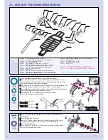
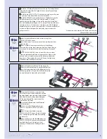
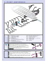
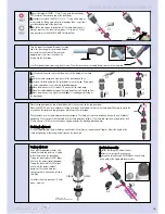
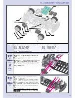
Thread one #309358 (SB M4x8) downstop adjustment screw into

the rear lower arm. It must protrude 2.6 mm. This screw needs to be
accessible from the top of the arm.

2

2..

Thread one #309351 (SB M3x4) pivot pin set screw into the arm.

Thread it just enough so it will stay in the hole; don't let it thread into
the pivot pin area.

3

3..

Thread one #309354 (SB M3x8) shock mounting screw into the

hole located on the outside of the arm. It must protrude 3.0 mm.

RReeppeeaatt  ffoorr  tthhee  ootthheerr  aarrm

m,,  m

maakkiinngg  ssuurree  ttoo  m

miirrrroorr  tthhee  ssccrreew

w  ppllaacceem

meenntt..

1

1..  

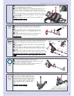
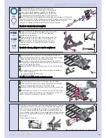
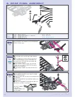
Position the rear suspension arm in the rear bulkhead. It should seat between the two plastic lower

suspension holders. Note that the pivot pin set screws should be seen from underneath the chassis.

2

2..  

Align the holes in the arms with the suspension holders and slide

a rear pivot pin through the hole to secure them. The flat spot on the
pivot pin must be towards the rear and facing the bottom.

3

3..  

Tighten the #309351 (SB M3x4) pivot pin set screw 

just until it touches the pivot pin.

4

4..  

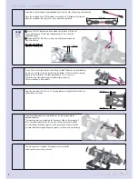
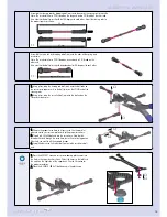
Once both pivot pins are installed, tighten all the screws that

were left loose in section 02 Rear Transmission:
-- Bulkhead brace #309354 (SB M3x8) screws
-- Lower chassis #309343 (SFH M3x6) screws
-- Lower suspension holders

A

Afftteerr  aallll  tthhee  ssccrreew

wss  aarree  ttiigghhtt,,  cchheecckk  tthhee  aarrm

mss  ffoorr  ffrreeee  m

moovveem

meenntt..

305310

305230

305320

305240

309452

307352

307354

307350

303310

309054

309425

303111

303115

OPTION

307351

OPTION

305315

OPTION

303230

302080

303240

303210

303220

307310

309354

309351

309358

309333

309351

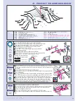
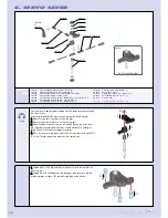
3. REAR SUSPENSION

30 2080

CASTER CLIPS SET - 4,3,2,1 MM  (2)

30 3111

SUSPENSION ARM REAR LOWER EVO2

30 3115

ALU REAR LOWER ARM 3 SHOCK POSITIONS (OPTION)

30 3200

ADJ. REAR TURNBUCKLE L/R 25 MM - SPRING STEEL (2+4)

30 3210

REAR TURNBUCKLE L/R 25 MM - SPRING STEEL  (2)

30 3220

BALL JOINT 5.8 MM (4)

30 3230

ADJUSTABLE 5.8 MM BALL END - SPRING STEEL  (2)

30 3240

BALL UNIVERSAL 5.8 MM HEX  (4)

30 3310

UPRIGHT REAR

30 5230

DRIVE SHAFT COUPLING - SPRING STEEL  (2)

30 5240

DRIVE SHAFT REPLACEMENT PLASTIC CAP 3 MM  (4)

30 5310

WHEEL AXLE REAR - INTEGRATED HEX HUB - HARD COATED  (2)

30 5315

WHEEL AXLE REAR WITH HEX HUB - SPRING STEEL (2)  (OPTION)

30 5320

DRIVE SHAFT REAR - SPRING STEEL  (2)

30 7310

REAR WISHBONE PIVOT PIN BOTTOM - SPRING STEEL  (2)

30 7350

PIVOT BALL 6.8 MM - SPRING STEEL  (2)

30 7351

ALU PIVOT BALL 6.8 MM - HARD COATED (4)

30 7352

ALU ADJUSTING NUT M8 x 1  (4)

30 7354

PLASTIC BALL CUP 6.9 MM  (4)

30 9054

HIGH-SPEED BALL-BEARING 10 x 15 x 4 BLUE COVERED (2)

30 9333

HEX SCREW  SH M3x6  (10)

30 9351

HEX SCREW  SB M3x4 (10)

30 9354

HEX SCREW  SB M3x8 (10)

30 9358

HEX SCREW  SB M4x8 (10)

30 9452

PIN 2x10  (10)

30 9425

O-CLIP 10  (10)

309354

SB M3x8

309351

SB M3x4

309358

SB M4x8

BAG

03

2.6 mm

3.0 mm

Содержание T1 EVO2

Страница 1: ......

Страница 2: ...assembly steps again to ensure all parts have been used properly We have made every effort to make the instructions and Set Up Book as easy to understand as possible However if you have any difficulti...

Страница 3: ...hread in the plastic We recommended you stop tightening a screw when you feel some resistance Ask your local hobby shop for any advice Please support your local hobby shop We at XRAY Model Racing Cars...

Страница 4: ...Bo oo ok k 1 1 The diff locknut is pre installed in the short diff output shaft If you need to replace the diff locknut push it out from the opposite side with the tip of a wrench Insert a new one int...

Страница 5: ...a at t a allll t th he e s st te ep ps s t to o b bu uiilld d a a s se ec co on nd d d diif ff fe er re en nt tiia all Tighten the diff until you feel some resistance To check the diff hold both wrenc...

Страница 6: ...r the small ball bearings into the bulkheads as shown The plastic holder with the hole through it goes in the right bulkhead the plastic holder without the hole through it goes in the left bulkhead 2...

Страница 7: ...Install the two 309314 ST 6x12 cone washers making sure they face the right way Check the detail for the correct orientation 8 8 Install the 30 5540 one way adjustment nut Thread the nut onto the lay...

Страница 8: ...on holders A Af ft te er r a allll t th he e s sc cr re ew ws s a ar re e t tiig gh ht t c ch he ec ck k t th he e a ar rm ms s f fo or r f fr re ee e m mo ov ve em me en nt t 305310 305230 305320 305...

Страница 9: ...on both sides of the wheel axle 4 4 Install the plastic cap onto the drive shaft pin First insert one hole of the plastic cap over a pin then stretch the other hole over the other pin R Re ep pe ea a...

Страница 10: ...ads The holes in the arm are pre tapped for easy installation Turn each pivot ball only 1 2 turns at a time Position the drive shaft s plastic cap in the differential outdrive slot Continue threading...

Страница 11: ...SPENSION HOLDER SET 2 1 1 30 2053 ALU LOWER SUSP HOLDER 30 2060 FRONT UPPER SUSPENSION HOLDER SET 4 8 30 2065 ALU ECCENTRIC FRONT UPPER PIVOT PIN HOLDERS 4 30 2070 ECCENTRIC NYLON HUB FOR BULKHEAD COV...

Страница 12: ...4 HEX SCREW SB M3x8 10 30 9358 HEX SCREW SB M4x8 10 30 9425 O CLIP 10 10 30 9452 PIN 2x10 10 Remove any excess plastic flash from the holes in the steering blocks before beginning assembly 1 1 Insert...

Страница 13: ...flat on a table Put one end of the snap ring into the groove on the opposite side of the wheel axle cutout and use a slotted screwdriver to work the rest of the clip into the groove R Re ep pe ea at t...

Страница 14: ...snaps into a groove on the steering post 1 1 Thread a 30 2650 ball end into the lower servo saver Be sure that the ball is on top 2 2 Thread two 30 2650 ball ends into the upper servo saver arm into...

Страница 15: ...n 2 2 Thread a 302650 ball end into the servo horn Note that the thread will extend through the servo horn but will not affect operation If desired you can file off the exposed threads 3 3 Snap the ot...

Страница 16: ...4 XRAY SPRING SET D 1 4 WHITE SOFT OPTION 30 8395 XRAY SPRING SET D 1 5 BLUE SOFT MEDIUM OPTION 30 8396 XRAY SPRING SET D 1 6 VIOLET MEDIUM OPTION 30 8397 XRAY SPRING SET D 1 7 PURPLE MEDIUM HARD OPTI...

Страница 17: ...cks fully extend the shock rod and turn it slightly to lock the piston in the shock body Turning the shock rod fully CCW aligns 4 holes in the pistons softest damping Turning the shock rod fully CW al...

Страница 18: ...SET 30 3091 ULTRA TUNE SHOCK TOWER REAR 2 5 MM GRAPHITE 30 9333 HEX SCREW SH M3x6 10 30 9334 HEX SCREW SH M3x8 10 30 9335 HEX SCREW SH M3x10 10 30 9393 NUT M3 10 30 9452 PIN 2x10 10 30 8300 XRAY SHOCK...

Страница 19: ...ER 2 5 MM GRAPHITE CNC MACHINED 30 1320 FRONT BODY MOUNTS SET 30 2092 SHOCK TOWER FRONT 2 5 MM FOR LARGER TIRES 30 9333 HEX SCREW SH M3x6 10 30 9345 HEX SCREW SFH M3x10 10 30 1200 NYLON BUMPER 30 1220...

Страница 20: ...e ball ended battery holder mounts with battery straps to the chassis with 309343 SFH M3x6 screws Orient the mounts so the battery will fit in the cutout Note If there is a lot of play between the bat...

Страница 21: ...cure it with the 309350 SB M3x3 set screw 3 3 Put one 309317 S 3 2 washer each on two 309334 SH M3x8 screws Use these to mount the motor to the right rear bulkhead 4 4 Adjust the motor and the pinion...

Страница 22: ...orientation of the washer in the illustration Make sure the wheel screws are very tight so the wheels do not come loose during racing The XRAY T1 EVO2 is a top competition racecar and therefore does n...

Страница 23: ...tructions correctly Over charging or charging incorrectly using inferior chargers can cause the batteries pack to become dangerously hot Regularly check the charger for potential hazards such as damag...

Отзывы: