12
1
1..
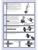
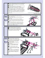
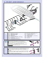
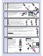
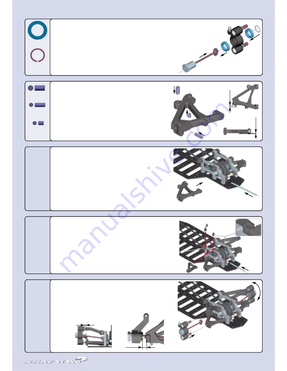
Thread one #309358 (SB M4x8) downstop adjustment screw into the
front lower arm. It must protrude 1.3 mm. This screw needs to be
accessible from the top of the arm.
2
2..
Thread one #309354 (SB M3x8) shock mounting screw into the hole
located on the outside of the arm, as shown. It must protrude 3.0 mm.
3
3..
Thread one #309351 (SB M3x4) pivot pin set screw into the arm.
Thread it just enough so it will stay in the hole; don't let it thread into
the pivot pin area.
RReeppeeaatt ffoorr tthhee ootthheerr aarrm
m,, m
maakkiinngg ssuurree ttoo m
miirrrroorr tthhee ssccrreew
w ppllaacceem
meenntt..
1
1..
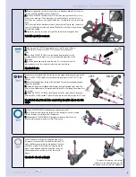
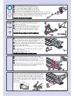
Position the upper front suspension arms in the upper suspension holders.
2
2..
Slide a #307230 front upper pivot pin through the aligned holes in the holders
and the arm. The flat spot on the pivot pin must be towards the side.
3
3..
Tighten the #309351 (SB M3x4) pivot pin set screws just until they touch the pivot
pins.
4
4..
Install the caster clips. Use only 3 mm, 2 mm and 1 mm clips. The initial setting is
to install one 2 mm clip in front of each arm, and install two clips (1 mm and 3 mm
clip) behind each arm. For adjustment, refer to the Set-Up Book.
1
1..
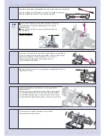
Slide a #309054 (BB 10x15) ball-bearing onto the wheel axle.
2
2..
Insert the drive shaft through the steering block until the bearing on
the axle is seated. Note the direction of installation from the diagram.
3
3..
Slide another #309054 (BB 10x15) ball-bearing over the drive shaft.
Press the bearing into the steering block, making sure that it fits precisely.
4
4..
Fasten the wheel axle to the steering block by installing a snap ring in the groove in the wheel axle
(near the drive shaft joint). To make installation easier, place the hex portion of the wheel axle flat on
a table. Put one end of the snap ring into the groove on the opposite side of the wheel axle
cutout, and use a slotted screwdriver to work the rest of the clip into the groove.
RReeppeeaatt ffoorr tthhee ootthheerr w
whheeeell aaxxllee aanndd sstteeeerriinngg bblloocckk..
1
1..
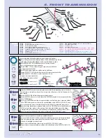
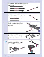
Position the lower front suspension arm in the front bulkhead. It should seat
between the two plastic lower suspension holders. Note that the pivot pin set screws
should be accessible from the 9mm holes underneath the chassis.
2
2..
Align the holes in the arms with the suspension holders and slide a #307212
lower front pivot pin through the aligned holes. The flat spot on the pivot pin must be
towards the rear and facing the bottom.
3
3..
Tighten the #309351 (SB M3x4) pivot pin set screw just until it touches the pivot
pin.
4
4..
Once both pivot pins are installed, tighten all the screws that were left loose in
section 04 Front Transmission:
-- Lower chassis #309343 (SFH M3x6) screws
-- Lower suspension holders
A
Afftteerr aallll tthhee ssccrreew
wss aarree ttiigghhtt,, cchheecckk tthhee aarrm
mss ffoorr ffrreeee m
moovveem
meenntt..
➊
➋
➌
➍
➊
➋
➊
➋
➌
➍
➊
➋
➌
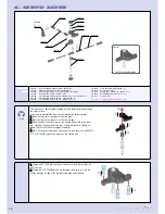
FRONT SUSPENSION
3.5mm
3.0
mm
1.3
mm
309054
BB 10x15
309425
C 10
309358
SB M4x8
309354
SB M3x8
309351
SB M3x4
Make sure that the whole assembly moves freely and easily.
6.0mm
Insert a 2.5mm hex wrench into the ends of the steering block pivot balls. Thread the
two pivot balls into the arms just enough so they are secured by a few threads. The
holes in the arms are pre-tapped for easy installation. Turn each pivot ball only 1-2
turns at a time. Position the drive shaft's plastic cap in the differential outdrive slot.
Continue threading in the pivot balls until there is a gap between the upper and lower
portions of the steering block and the ends of the suspension arms, as shown in the
detail illustration.
The front suspension is complete.
3mm
2mm
1mm
Содержание T1 EVO2
Страница 1: ......


