background image

11

7.1.3 Adjusting Voltage and Current


The voltage and current are set using the two controls labeled “VOLTAGE” and “CURRENT”.  These controls use high quality 
digital encoders rather than potentiometers.  Turn the controls clockwise to increase a setting or counter clockwise to decrease 
a setting.    The encoders allow fine or coarse control of the voltage or current setting.  The speed at which you turn the controls 
will determine the granularity of the setting.  Turning at a slow rate will adjust the least significant digit of the parameter being 
adjusted.  Turning more rapidly allows coarse control to allow rapid changing of voltage or current.   
 
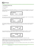
If the output is disabled while an adjustment is being made the voltage and current setting will be shown on the normal output 
off display.  The new settings will take effect when the output on/off button is pressed. 
 
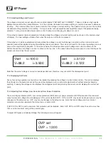
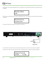
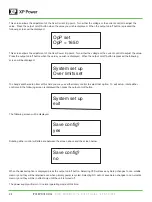
If the output is on while an adjustment is being made the voltage or current will change in real time as the control is turned. A 
special screen will be displayed during the adjustment as shown below.  The screen will revert to the normal operating screen as 
soon as the adjustment is complete.  In the screens below the actual real-time output voltage and current is shown on the 
bottom line and the set voltage or current is shown in the top line.  In the cases below the power supply is current limiting as the 
actual current matches the set current. 
 

Note that the actual voltage or current is load dependent and, therefore, may not match the displayed set point. 
 

7.1.4 Displaying Set Points


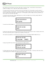
At any time during operation, set points can be recalled by pressing the voltage or current rotary control.  This action displays 
the set points in the same manner as they would be displayed during a set point adjustment but without actually changing 
anything.  Pressing the voltage control displays the voltage set point and pressing the current control displays the current set 
point. 
 

7.1.5 Adjusting Over Voltage, Over Current and Over Power Protection.


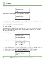
The over voltage protection (OVP), over current protection (OCP) and over power protection (OPP) features limit the maximum 
output current and voltage to avoid damages to the unit under test (UUT).  OVP and OCP may be set as shown below or may be 
changed via the setup menus.  OPP may only be changed in the setup menus.  Note that Over Voltage and Over Current 
protection can also be adjusted in the Setup menu – section 8.2.5. 
 
If OVP, OCP, or OPP is set to maximum that protection will be disabled.  Note: OVP, OCP, and OPP cannot be set to more than 
10% over the maximum rating of the power supply. 
 
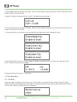
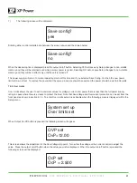
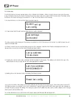
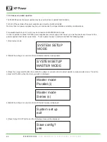
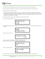
To adjust OVP press and release Voltage. The following screen will appear: 

Vset

v=100.0

V=88.2  

i=3.500

OVP set 

OVP = 12.00

iset

i=3.122

V=88.2  i-3.122

Содержание PLS1500 Series

Страница 1: ...uctive parts including control controls can render an electric shock The power jack and mating plug of the provided power cable meet IEC safety standards DO NOT OPERATE IN AN EXPLOSIVE ATMOSPHERE Do not operate the instrument in the presence of flammable gases or fumes Operation of any electrical instrument in such an environment constitutes a definite safety hazard KEEP AWAY FROM LIVE CIRCUITS In...

Страница 2: ... line cord to the AC mains check the top cover AC line voltage ratings Applying a line voltage other than the indicated voltage can damage the unit For continued protection replace fuses only with those of the exact same voltage and current ratings CAUTION This product uses components which can be damaged by electro static discharge ESD To avoid damage be sure to follow proper procedures for handl...

Страница 3: ... Instructions 10 7 1 Normal operation 10 7 1 1 Power on 10 7 1 2 Enabling output 10 7 1 3 Adjusting voltage and current 11 7 1 4 Displaying set points 11 7 1 5 Adjusting over voltage over current and over power protection 11 7 2 Power Supply Set Up 12 7 2 1 Introduction 12 7 2 2 Mode 14 7 2 3 Auto start setup 16 7 2 4 Remote sense setup 17 7 2 5 Power limit setup 20 7 2 6 Over limits 21 7 2 7 LAN ...

Страница 4: ...rams on command Details can be found in the PLS1500 scripting language manual 4 2 Features 1 Output Voltage Current 2 Rotary Controls The digital rotary controls allow both fine and rapid adjustment of the output voltage and current The controls are velocity sensitive so that a slow turn of the control allows fine adjustment of voltage or current and rapid turning quickly adjusts voltage or curren...

Страница 5: ...10 11 Voltage 30 V 50 V 100 V 200 V 400 V Current 70 A 40 A 20 A 10 A 5 A Power 1500 W 1500 W 1500 W 1500 W 1500 W Output Ripple Noise CV p p 3 45 mV 75 mV 100 mV 200 mV 300 mV CV rms 4 10 mV 20 mV 40 mV 80 mV 100 mV Load Regulation change from 10 90 load Voltage 0 05 0 05 0 05 0 05 0 05 Current 0 05 0 05 0 05 0 05 0 05 Line Regulation change from 100 132 VAC input or 180 260 VAC input 1 Voltage 0...

Страница 6: ...ion Altitude Up to 3000 meters Derate the output current by 2 100 m above 2000 m Ambient temperature Derate the maximum ambient temperature by 1 C 100 m above 2000 m Regulatory compliance EMC European EMC directive 89 336 EEC for Class A products This ISM device complies with Canadian ICES 001 Safety European Low Voltage Directive IEC 60950 US and Canadian safety standards Any LEDs used in this pr...

Страница 7: ...t least 1 inch of open space at the vents with good ventilation If the units are stacked do not block the side air intakes Never block the rear air outlets 3 The product is designed with a power line filter to minimize noise into the instrument from the AC power source and to minimize noise output to the line The power supply is also protected from moderate power transients and ESD on its terminal...

Страница 8: ...accuracy calibration should be performed annually 5 7 Power off procedure When the supply is not in use be sure to turn the power switch on the panel to the OFF position to turn off the AC power After the power switch is turned to the OFF position the inner fans will still run for up to 15 seconds Once the discharge process is complete the power supply will shut down 5 8 Low Voltage Input When the...

Страница 9: ... significant digit of the displayed setting As the control is turned faster more significant digits will be incremented When the output is activated pressing this control will display Set Voltage 4 Output On Off Button Pushing this button after the power to the power supply has been turned on enables the output voltage Pressing and holding this button for more than 5 seconds and then releasing wil...

Страница 10: ... and the display will show the output status the operating mode and the actual output voltage and current on vmode Ioc V 100 0 i 1 654 The power supply will always be in either voltage mode VMODE or in current mode IMODE or PMODE This state is dependent on the power supply settings and the load When in current mode the display will be as shown below To disable the output simply press the output on...

Страница 11: ...voltage or current is shown in the top line In the cases below the power supply is current limiting as the actual current matches the set current Note that the actual voltage or current is load dependent and therefore may not match the displayed set point 7 1 4 Displaying Set Points At any time during operation set points can be recalled by pressing the voltage or current rotary control This actio...

Страница 12: ...below Pressing Output On Off when any of the trip screens are displayed will reset the trip and put the power supply back in idle mode The following screen will be displayed Pressing Enable at this time will turn on the output OcP set OcP 2 500 Overvoltage trip Enable to reset System set up mode Overcurrent trip Enable to reset Overpower trip Enable to reset Off Ioc V 100 0 i 3 500 7 2 Power Suppl...

Страница 13: ...ugh the setup options by rotating either control System set up mode System set up Auto start System set up Remote sense System set up POWER SETPOINT System set up Over limits set System set up LAN CONFIG System set up MSTER MODE System set up CALIBRATION System set up exit ...

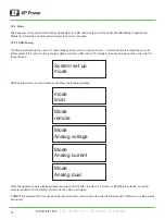
Страница 14: ...ntrol or USB control The Mode screen shown below is the entry point for these choices System set up mode mode local Mode remote Mode Analog voltage Mode Analog current Mode Analog dual Rotating either rotary control clockwise will show the following screens When the desired mode is displayed press the output on off button to select it If LOCAL or REMOTE is selected no further setup is required and...

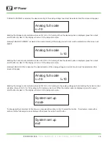
Страница 15: ...n is displayed press the output on off button to select it The display will return to the setup main menu Similarly ANALOG DUAL is selected the desired scaling of the analog voltage and current inputs must be selected and this screen will appear System set up mode System set up exit Rotating the Voltage control will allow choice of 3V 5V or 10V scaling for the analog voltage port and rotating the ...

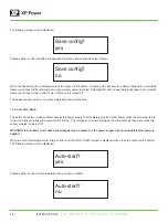
Страница 16: ... and they will be in effect only until the unit is turned off The power supply will return to normal operating mode at this time 7 2 3 Auto Start Setup The Auto Start option when enabled causes the power supply to immediately provide output power when the power switch is turned on without pressing the output on off button The voltage and current settings will be the same as they were when the supp...

Страница 17: ...and they will be retained even when primary power is cycled Selecting NO will not save Setup changes to non volatile memory and they will be in effect only until the unit is turned off The power supply will return to normal operating mode at this time 7 2 4 Remote Sense Setup Most power supplies with remote sense require a second set of wires between the power supply and the load to sense the volt...

Страница 18: ... the system will revert to the Setup main menu If the YES option is selected the following screen will be displayed At this point the load end of the wires must be shorted as shown below It is important that a good short with heavy wire is made as failure to do this will result in a poor remote sense calibration Once the short is in place press the output on off button The following screen is an e...

Страница 19: ...either control until the following screen is displayed then press the output on off button Now set the current to at least as much as you would expect your load to consume More is better if your load wires are capable of handling the current When ready press the output on off button The power supply will now measure the output current and the total voltage drop in the load wires and use these valu...

Страница 20: ... PLS1500 power supply is designed to supply up to 600 watts of output power to a load In some applications it may be desirable to limit the maximum power to something lower than the maximum available from the power supply This section describes how to set up power limiting 1 Enter setup mode 2 Rotate the voltage or current control until the following screen appears 3 Push the output on off button ...

Страница 21: ...tup changes to non volatile memory and they will be retained even when primary power is cycled Selecting NO will not save Setup changes to non volatile memory and they will be in effect only until the unit is turned off The power supply will return to normal operating mode at this time and if you selected Save Config Yes then the new power limit will be in effect To remove the power limit the same...

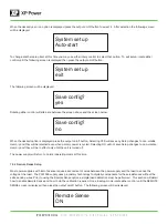
Страница 22: ...en will be displayed System set up exit To change another setup item at this time you may use either rotary control to select that option To exit setup rotate either control until the following screen is displayed then press the output on off button Save config yes Save config no The following screen will be displayed Rotating either control will alternate between the screen above and the screen b...

Страница 23: ...ing screen If you wish to reset the LAN settings to the factory default press the output on off button again Now rotate either control until the following screen your selection of Yes or No is displayed Pressing Output On Off button once again while Yes is displayed will reset the power supply LAN settings This feature is useful if the IP address has been set to a static address and is no longer a...

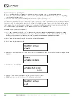
Страница 24: ...master and the rest of the power supplies must be set up as slaves To put a power supply in master mode take the following steps 1 Enter setup mode SYSTEM SETUP MODE SYSTEM SETUP MASTER MODE 2 Rotate the voltage or current control until Master Mode screen appears Master mode Parallel i Master mode Series v 3 Press the output on off button then rotate the voltage or current control to select parall...

Страница 25: ...oltage that will be output by the slave when following the master All slaves should be set to this same maximum voltage 2 Put the power supply in analog current control mode by taking the following steps a Put the power supply is setup mode Mode Analog current Analog full scale 1 10 b When MODE is displayed press the output on off button then rotate the voltage or current control until the followi...

Страница 26: ...tput by the paralleled supplies divided by the number of supplies in parallel For series supplies take the following steps 1 On the slave supply set the current to the maximum current that will be desired in the application Note that this voltage setting on the slave will not be the actual current output The actual current output will be determined by the master This setting will only determine th...

Страница 27: ...oltage and current will be determined by the master supply Adjusting the voltage on the master will adjust the outputs on the slave supply As the load changes the voltage will be shared between the supplies Note that the voltage setting on the master will reflect the actual voltage output by the series supplies divided by two 7 2 9 Calibration Power supply calibration allows qualified personnel to...

Страница 28: ...following screen will be displayed At this point only a volt meter should be connected to the output No load should be connected See illustration below Output Open load When the volt meter is connected press the output on off button The following screen is an example of what will appear Set voltage to 10 0 volts ...

Страница 29: ...ill appear Set voltage to 100 0 volts Again using the Voltage control adjust the output until the external volt meter reads exactly the voltage displayed on the power supply display Note that the voltage displayed on the screen will vary depending on the power supply model When the two voltages match exactly press the output on off button and the following screen will appear Now a current shunt mu...

Страница 30: ... volts Note also that the current displayed on the screen will vary depending on the power supply model When the current is exactly correct press the output on off button and the following screen will appear Set current to 0 1500 amps Set current to 6 00 amps Using the same formula as above the voltage reading on the volt meter should be 0 030 volts for this example when the supply is set correctl...

Страница 31: ...displayed press the output on off button Selecting YES will save any Setup changes to non volatile memory and they will be retained even when primary power is cycled Selecting NO will not save Setup changes to non volatile memory and they will be in effect only until the unit is turned off The power supply will return to normal operating mode at this time Save config no ...

Страница 32: ...follows The connector physical pinout is shown below The correct mating connector is an On Shore Technology Inc 5 pin connector such as their part number OSTTJ0531530 To use a potentiometer as the control source connect one end of the potentiometer to the 3 0 Volt Reference the other end to Ground and the wiper to the control Input The potentiometer should be in the range of 1K to 10K ohms Set the...

Страница 33: ...n location wiill be required in later steps The standard USB input is a USB 2 0 full speed compatible USB port To install the USB drivers make sure the unit is powered on the PLS1500 unit is connected to the computer s USB port Open Device Manager and locate the PLS1500 SUPPLY under other devices Right click on the PLS1500 SUPPLY and select properties On the driver tab select Update Driver ...

Страница 34: ...e where the PLS1500 supply USB drive was extracted to and click next Once the driver has been successfully installed windows will verify the installation and the PLS1500 Supply can now be accessed through the USB communication ...

Страница 35: ...e Web server you can access the front panel control functions including the LAN configuration parameters Up to two simultaneous connections are allowed With additional connections performance will be reduced NOTE The built in Web server only operates over the LAN interface It requires Internet Explorer 7 or Firefox2 or Chrome The Web server is enabled when shipped To launch the Web server 1 Open t...

Страница 36: ...he front panel the power supply should be put into remote mode as described below 1 Enter setup mode and the push the output on off button on the following screen 3 When REMOTE is displayed press the output on off button Note that when in remote mode all menu selections other than REMOTE or LOCAL are suppressed 4 Exit and Save the setting Controlling your power supply using TCP IP or UDP IP Your p...

Страница 37: ... no changes to the unit If the customer wishes to remove the rubber feet that is OK Retain the feet and screws in case they are needed later CAUTION If the feet are replaced with the incorrect screws damage to the power supply can occur Be sure to use 6 32 screws with 3 8 inch length ...

Страница 38: ...Enable to reset Temperature err Enable to reset The OVERVOLTAGE TRIP error is caused by exceeding the voltage set by the OVP SET command If the voltage limit value is set to below the OVP SET value this condition will rarely if ever occur If the OVP SET value is below the voltage limit value then this condition will occur whenever the load resistance is high enough to allow the set value to be exc...

Страница 39: ... to reset The 3 3V BIAS ERR error is an internal error of the power supply This is usually caused by a component failure To reset the power supply simply press the Output On Off button If the error reoccurs the power supply must be repaired by the factory The PFC FAILURE error is an internal error of the power supply This is usually caused by a component failure To reset the power supply simply pr...

Страница 40: ...OR error is an internal error of the power supply that can occur during initial power on when the self test is performed The unit must be sent in to the factory for repair COMM TIMEOUT Enable to reset COMM TIMOUT indicates that one of the power supplies communication ports has not responded in a timely manner To reset the power supply simply press the Output On Off button ...

Страница 41: ...ible return the unit in its original packaging Do not return the power cord or USB stick Please include the RMA number with the unit being returned Units must be well packaged when shipping to XP Power the repair of any damage incurred during shipping is not covered by warranty and will be charged to the customer Return all units to XP Power using pre paid shipping For warranty repairs XP Power co...

Страница 42: ...ion and handling charge will be applied This warranty is in lieu of all other warranties obligations and liabilities either expressed or implied and are the purchaser s exclusive remedy XP Power makes no warranty either expressed or implied of merchantability fitness for a particular purpose or otherwise In no event shall XP Power be liable whether in contract tort or negligence for special indire...

Отзывы: