5
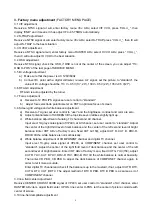
a) field amplitude adjustment
Receive PERCENT OVERSCAN signal of VP403, set user control to “standard” of AV channel, enter
RASTER ADJ item, adjust field amplitude V-SIZE, let the vertical reproduction ratio of picture acceptable
5%.
b) line amplitude adjustment
receive PERCENT OVERSCAM single of VP403, set user control to “standard” of AV channel.
13” and 20”: adjust B+ potentiometer RP502, let the line reproduction ratio of picture acceptable 5%.
20”, 24” and 27”: enter RASTER ADJ item, adjust line amplitude H-SIZE, let the line reproduction ratio of
picture acceptable 5%.
3.11 line, field linearity and geometry adjustment
receive CROSSHATCH single of VP403, set user control to “standard” of AV channel.if the linearity and
geometry are not satisfied, you may adjust the following items of RASTER ADJ:
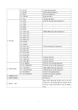
Corner PARA
Trape VS-CORE V-LIN
Note: CORNER, PATR, TRAPE need not adjust at 13” and 20”.
4. Checking point
4.1 High voltage check
Connect High Voltage meter between CRT second anode and GND.
1) Receive A7 signal, set user control to “STANDARD”, measure the high voltage value, the reading
should be the value below:
13”: 22 kV
±
1 kV 20”: 25.5 kV
±
1 kV
24”: 27 kV
±
1 kV 27”: 29kV
±
1 kV
2) Set the brightness and contrast to minimum (zero beam current), measure the high voltage, the
reading should not exceed 33kV.
4.2 CRT filament voltage check
Receive A7 signal, set picture to “STANDARD”, use effective voltage meter to measure CRT filament
voltage, the reading should be (6.3
±
0.3) Vrms
4.3 X-ray protection check
1) Receive A7 signal, set user control to “vivid”.
2) 13”, 20”, 24”: Short circuit R309 (TP302, TP303), X-Ray protection circuit should function.
27”: press S301, X-Ray protection circuit should function.
4.4 Picture and sound check
1) Receive standard TV signal, include NTSC and ATSC.
2) Use picture control buttons to check color, contrast, brightness, sharpness, tint’s function.
3) Use sound control buttons to check volume control function.
4.5 Sub-brightness, sub-contrast check
1) sub-brightness check
Receive full-screen 8IRE signal of VP403, set user control to “standard” and check if it is satisfied (for
example: BESTBUY require brightness of 7.5IRE BLACK
≤
0.20 ft.L), if not, enter PICTURE ADJ item.
AV channel: ATV BRIGHT
COMPONENT channel: YUV BRIGHT
DTV channel: DTV BRIGHT
Fine adjust the items to let it be satisfied (suggest 0.15 ft.L
≤
BLACK brightness
≤
0.20 ft.L).
2) sub-contrast check
Receive window 100IRE signal of VP403, set user control to “standard” and check if it is satisfied (for
Содержание TQ2426
Страница 1: ...COLOR TELEVISION TQ2426 ...
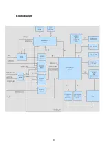
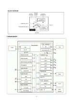
Страница 11: ...Block diagram 9 ...
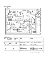
Страница 12: ...10 IC Block diagram 1 R2J1016XFP ...
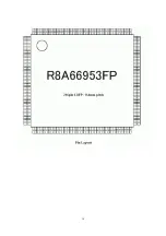
Страница 15: ...13 5 R8A6695SFP ...
Страница 16: ...14 ...
Страница 17: ...15 ...
Страница 20: ......
Страница 21: ......
Страница 22: ......
Страница 24: ...603 TQ24260 10 Ver 1 0 ...

