4
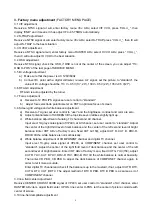
3. Factory menu adjustment
(FACTORY MENU PAGE)
3.1 VIF adjustment
Receive a NTSC signal at will, enter factory menu VCJ ADJ, select VIF VCO, press “VOL+/_”, then
display “END” and it means IC has adjust IF to 45.75MHz automatically.
3.2 S-TRAP adjustment
Receive a NTSC signal at will, enter factory menu VCJ ADJ, select S-TRAP, press “ VOL+/_”, then IC will
adjust S-TRAP to the best situation.
3.3 H VCO adjustment
Receive a NTSC signal at will, enter factory menu RASTER ADJ, select H VCO ADJ, press “ VOL+/_”,
then IC will auto adjust H VCO to the best situation.
3.4 OSD adjustment
Receive NTSC signal, check the OSD, if OSD is not at the center of the screen, you can adjust ”110:
OSD H-POS” of the last page of SERVICE MENU.
3.5 B+ voltage adjustment
a) Make sure that the power is AC 120V/60Hz
b) Connect B+ point with a digital voltmeter, receive A-7 signal, set the picture to “standard”, the
value of B+ voltage should be 110 V
±
0.5 V(13”, 20”), 130V
±
0.5 V(24”), 135V
±
0.5 V(27”).
3.6 RF AGC adjustment
RF AGC is auto adjusted by the turner.
3.7 Focus adjustment
a) Receive A-12 PHILIPS signal, set user control to “standard”.
b) Adjust focus electrode potentiometer on FBT to optimize focus of screen.
3.8 Screen-grid voltage and white balance adjustment
a) Receive A-7 signal, set user control to “user” and the brightness, contrast and color are zero.
b) Adjust potentiometer of SCREEN till the top side seven lattices slightly light up.
c) White balance adjustment of analog TV channel and AV channel.
Input erect 10-gray scale signal of VP403, at AV channel, set user control to “standard”. Adjust
the center of the right third level of dark balance and the center of the left second level of bright
balance. Enter CRT ADJ of factory menu, fixed CUT G(150), adjust CUT R, CUT B, DRV-R,
DRV-B till the white balance is normal basically.
d) White balance adjustment of COMPONENT channel and digital TV channel.
Input erect 10-gray scale signal of VP403, at COMPINENT channel, set user control to
“standard”. Adjust the center of the right third level of dark balance and the center of the left
second level of bright balance. Enter CRT ADJ of factory menu, fixed CUT G YUV(150), adjust
CUT R YUV, CUT B YUV, DRV-R YUV, DRV-B YUV till the white balance is normal basically.
Then enter CR PED, CB PED to adjust the dark balance of COMPONET channel again, in
order to let it more accurate.
Enter digital TV channel and check if the balance is up to the mustard, if not, adjust CUT R DTV,
CUT G DTV, CUT B DTV. The adjust method of DTV R PED, DTV B PED is as same as it of
COMPONENT channel
3.9 line, field center adjustment
Receive CENTER CROSS 100IRE signal of VP403, set user control to “standard” of AV channel, enter
RASTER ADJ item, adjust field center V-POS, line center H-POS, let the center of picture coincide with
center of screen.
3.10 line, field amplitude adjustment
Содержание TQ2426
Страница 1: ...COLOR TELEVISION TQ2426 ...
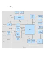
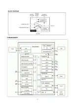
Страница 11: ...Block diagram 9 ...
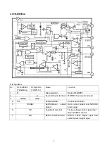
Страница 12: ...10 IC Block diagram 1 R2J1016XFP ...
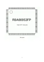
Страница 15: ...13 5 R8A6695SFP ...
Страница 16: ...14 ...
Страница 17: ...15 ...
Страница 20: ......
Страница 21: ......
Страница 22: ......
Страница 24: ...603 TQ24260 10 Ver 1 0 ...

