USER MANUAL
- OPTIMA-31 10K / 20K / 30K
www.xmart-ups.com
150615-OPT-31 10K/20K/30K (ENGLISH) - 23
START UP FOR PARALLEL UPS SYSTEM
WARNING: Make sure all requirements and previous inspection have been revised and complied before initiating start up procedure. If
not please do not try to continue with start-up procedure.
1.- Make sure all equipments to be protected and connected to UPS output are in OFF condition.
2.- Check AC input breaker located in UPS rear panels is in OFF position in all UPS of the system.
3.- Power on external main AC input in electrical panel. Set to ON position all external AC input breakers.
4.- If UPS are using external battery packs, set to ON all DC breakers to connect external DC packs to UPS.
5.- For UPS No. 1: Set to "ON" AC input breaker located in rear panel of UPS No. 1. Wait until UPS No.1 completes auto-checking and Bypass
LED lights continuously.
6.- For UPS No. 2: Set to "ON" AC input breaker located in rear panel of UPS No. 2. Wait until UPS No.2 completes auto-checking and Bypass
LED lights continuously.
7.-In case of having 3 UPS in the system, proceed in similar manner with UPS No. 3.
IMPORTANT: AC input breakers activation must be done in one by one and not at same time. First for UPS No. 1, then for UPS No. 2 and
finally for UPS No. 3 (if you have a parallel system with 3 UPS). If AC input breakers are activated all at same time, warning message "3F"
could be activated. If it occurs, reinitiate procedure sequentially. Warning 3F message must be previously reset according to warning and
error section in this manual
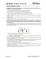
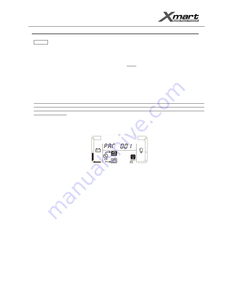
8.- When rear panel AC breaker is set to "ON", This UPS recognizes all other UPS previously powered ON in the parallel system and will get
its own parallel identification as PAR 00X, where X is the position according to power on sequence. PAR 001 for 1st UPS powered on, PAR
002 for 2nd and PAR 003 for 3rd UPS.
9.- At this moment all UPS LCDs must turn on to indicate internal circuitry in UPS is been powered.
** If bypass mode is allowed, all UPS will go to bypass mode.
** If bypass mode is not allowed by configuration, all UPS will go to a kind of stand-by mode with outputs open and powered off
waiting until ON command is selected in UPS front panel.
10.- At this moment configuration menu in each UPS LCD must be revised to select desired configuration. It is mandatory to use same
configuration in all configuration parameters for all UPS of the system.
11.- Once configuration has been selected and verified, all UPS can be started up by selecting "ON" push button in front panel. Please press
"ON" push button for each UPS. One long "beep" will be generated. "ON" message will be displayed on top side of LCD.
12.- All UPS will go to NORMAL Online mode at same time.
13.- Before setting to "ON" external output breakers please revise AC voltage output on each UPS.
** Please measure AC output voltage using a digital multi-meter and confirm all output voltages are similar. Maximum acceptable deviation
should be 3Vac or lower. Typically 1.5Vac.
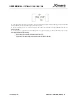
** If difference between output voltage values is higher than 3Vac, we suggest to adjust them by function 15. You can reduce (Sub) or
increase (Add) voltage output voltage for inverter in each UPS as required.


