background image


3. Driver interface 


3-1. Status indicator and troubleshooting 

The green LED is the power indicator. When the driver is powered on, the LED is always on; When the drive is 

powered off, the LED goes out. 

The red LED is the fault indicator. When there is a fault, the indicator will flash continuously, then  stop for one 

second, and then flash continuously. When the fault is cleared by the user, the red LED is always off. 

The  continuous  flashing  times  of  red  LED  represent  different  fault  information,  and  the  specific  relationship  is 

shown in the table below. The alarm output terminal outputs high level. 

Flashing times 

Fault   

Solution   

Over current or short 

circuit 

Check the power cable for short circuit 

Over voltage 

Check whether the power supply voltage is too high 

Under voltage 

Check whether the power supply voltage is too low 

Motor open circuit or 

poor contact 

Check whether the power cable is well installed or 

broken 

Position over limit 

Check whether the encoder cable is broken, check 

whether the motor is blocked, and increase the 

acceleration time appropriately 

Note: since the driver does not have the function of reverse connection protection of positive and negative poles of 

power  supply,  please  confirm  that  the  wiring  of  positive  and  negative  poles  of  power  supply  is  correct  again 

before power on. The reverse connection of positive and negative poles will burn out the safety tube in the driver. 


3-2. Upper computer communication interface 

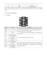
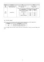
The definition of RS232 interface pin arrangement is as follows: 

Pin 

Function   

Note   

VCC 

Power  

WT 

Data write 

WR 

Data read 

Содержание DP3F Series

Страница 1: ...1 DP3F series closed loop stepping driver User manual Wuxi Xinje Electric Co Ltd Data No D3C05 202001215 1 0...

Страница 2: ...nual Statement of responsibility Although the contents of the manual have been carefully checked errors are inevitable and we can not guarantee that they are completely consistent We will always check...

Страница 3: ...iagram 7 2 2 2 Wiring notice 7 3 DRIVER INTERFACE 8 3 1 STATUS INDICATOR AND TROUBLESHOOTING 8 3 2 UPPER COMPUTER COMMUNICATION INTERFACE 8 3 3 CONTROL SIGNAL INTERFACE 9 3 3 1 Function 9 3 3 2 Contro...

Страница 4: ...g function can be set by switch It supports single and double pulse mode can be set by switch Support smoothing time can be set by switch and convenient for debugging and improves the stability of mot...

Страница 5: ...sional technicians 2 The input voltage of the driver must meet the technical requirements 3 It is strictly forbidden to plug the strong current terminal of the driver when the power is on When the mot...

Страница 6: ...6 2 Installation and wiring 2 1 Installation 2 1 1 Outline dimension DP3F 305 DP3F 705 Unit mm 31 77 110 102 6 4 21 8 5 2 4 3 4 3 DP3F 808 Unit mm 35 5 86 7 135 127 9 25 3 4 3 4 3 3 8 5 2...

Страница 7: ...pulse and direction signal cables and motor cables are not allowed to be bound side by side and it is better to separate them at least 10cm otherwise it is easy to interfere with the pulse direction s...

Страница 8: ...it 2 Over voltage Check whether the power supply voltage is too high 3 Under voltage Check whether the power supply voltage is too low 4 Motor open circuit or poor contact Check whether the power cabl...

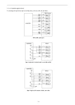
Страница 9: ...he upper computer according to the demand The rising edge is valid by default Note the input of 24V signal will damage the input terminal when 5 V is selected PUL DIR Direction control signal DIR ENA...

Страница 10: ...ol signal circuit Control signal input and output circuit diagram as shown in the figure below Differential mode input Input single ended common anode connection method Input single ended common catho...

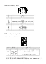
Страница 11: ...gnal 3 5 Motor and power supply interface 3 5 1 Strong current interface function Interface Function Explanation A A Motor phase A coil Cannot change direction by exchanging A A B B Motor phase B coil...

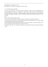
Страница 12: ...y is used the switching power supply output current range should be set to the maximum Note 1 Do not reverse the power supply voltage 2 Do not exceed the working range of the power supply to ensure th...

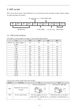
Страница 13: ...y upper computer 4000 On On On On 800 Off On On On 1600 On Off On On 3200 Off Off On On 6400 On On Off On 12800 Off On Off On 25600 On Off Off On 51200 Off Off Off On 1000 On On On Off 2000 Off On On...

Страница 14: ...et by the upper computer default 1 5ms ON ON 3ms ON OFF 12ms OFF ON Shut down the filter OFF OFF 4 2 5V 24V switch DP3F can select the 5V 24V pulse and the direction input level through this switch Th...

Страница 15: ...Internal pulse 0 1 0 Internal pulse operation mode 0 external pulse 1 internal pulse P0 05 0x0005 Open loop current percentage 1 100 50 Operating current in open loop mode Percentage of open loop cur...

Страница 16: ...rs Parameter Address Function Range Default Note P3 00 0x0300 Tracking error limit 1 65535 4000 1 turn P3 01 0x0301 Fault detection selection 0 65535 255 P3 02 0x0302 Under voltage alarm threshold 0 2...

Страница 17: ...P7 00 0x0700 Driver station no 1 100 1 P7 01 0 0x0701 0 1 Baud rate 03 2400 04 4800 05 9600 06 19200 07 38400 08 57600 09 115200 0A 192000 0B 256000 0C 288000 06 Default 19200bps 1 stop bit even parit...

Страница 18: ...phase feedback current mA U0 27 0x101B B phase feedback current mA U0 28 0x101C Reference feedback current mA U0 29 0x101D A phase set current mA U0 30 0x101E B phase set current mA U0 31 0x101F Refer...

Страница 19: ...06 Firmware generation date Day U2 07 0x1207 Software version U2 08 0x1208 Hardware version U2 09 0x1209 Power on operation time Hour U2 10 0x120A Power on operation time Minute U2 11 0x120B Power on...

Страница 20: ...on again Release signal is low Do not connect this signal Not power on Power on again Motor wiring error Check the wiring No pulse signal input Check the pulse cable and signal voltage Motor directio...

Страница 21: ...WUXI XINJE ELECTRIC CO LTD 4th Floor Building 7 Originality Industry park Liyuan Development Zone Wuxi City Jiangsu Province 214072 Tel 400 885 0136 Fax 510 85111290 www xinje com...

Отзывы: