


ZC706 Evaluation Board User Guide
56
UG954 (v1.5) September 10, 2015
Feature Descriptions
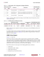
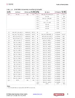
Status and User LEDs
defines the status and user LEDs.
Table 1-27:
Status LEDs
Reference
Designator
Net Name
LED Color
Description
DS1
POR
RED
Processor System Power-ON reset is active
DS2
FPGA_INIT_B
GRN/RED
Green: FPGA initialization was successful
Red: FPGA initialization is in progress
DS3
DONE
GRN
FPGA bit file download is complete
DS8
GPIO_LED_LEFT
GRN
Geographically LEFT located user LED
DS9
GPIO_LED_CENTER
GRN
Geographically CENTER located user LED
DS10
GPIO_LED_RIGHT
GRN
Geographically RIGHT located user LED
DS11
VCCINT
GRN
VCCINT voltage on indicator
DS13
VCC1V5_PL
GRN
VCC1V5_PL voltage on indicator
DS15
VADJ_FPGA
GRN
VADJ_FPGA voltage on indicator
DS16
VCC3V3_FPGA
GRN
VCC3V3 voltage on indicator
DS20
PS_DDR_LINEAR_PG
GRN
VTTDDR_PS voltage on indicator
DS21
SODIMM_DDR_LINEAR_PG
GRN
VTTDDR_SODIMM voltage on indicator
DS22
VCC12_P
GRN
VCC12_P voltage on indicator
DS23
PWRCTL1_FMC_PG_C2M
GRN
FMC power good INDICATOR
DS24
CTRL1_PWRGOOD
GRN
Power Controller controlled voltage regulator
outputs are all
≥
their minimum “good”
threshold
DS25
U22_FLG
RED
USB 2.0 MOSFET power switch fault
DS26
LINEAR_POWER_GOOD
GRN
MGTAVCC, MGTAVTT, MGTVCCAUX voltage
regulator outputs are all
≥
their minimum
“good” threshold
DS27
VCCAUX
GRN
VCCAUX voltage on indicator
DS28
PHY_LED0
GRN
Ethernet PHY LED0
DS29
PHY_LED1
GRN
Ethernet PHY LED1
DS30
PHY_LED2
GRN
Ethernet PHY LED2
DS35
GPIO_LED_0
GRN
General Purpose user LED


