KC724 GTX Transceiver Characterization Board
25
UG932 (v2.2) October 10, 2014
Detailed Description
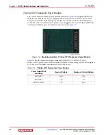
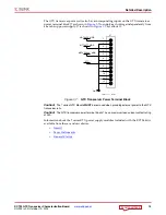
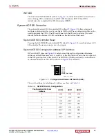
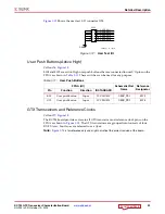
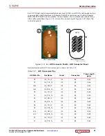
Each GTX Quad and its associated reference clocks (CLK0 and CLK1) are brought out to a
connector pad which interfaces with Samtec BullsEye connectors used with the Samtec
HDR-155805-01-BEYE cable assembly. Contact Samtec, Inc. for information about this or
other cable assemblies.
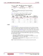
A
shows the connector pad.
B
shows the
connector pinout.
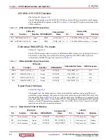
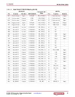
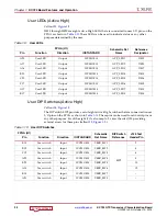
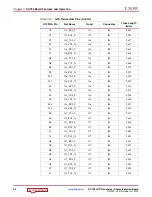
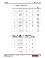
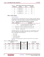
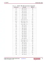
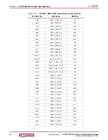
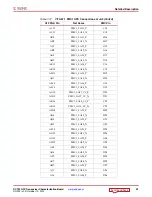
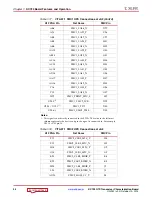
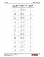
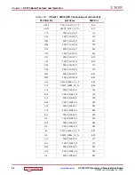
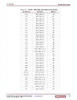
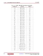
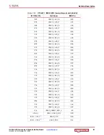
Information for each GTX transceiver pin is shown in
.
X-Ref Target - Figure 1-14
Figure 1-14:
A – GTX Connector Pad. B – GTX Connector Pinout
Table 1-12:
GTX Transceiver Pins
U1 FPGA Pin
Net Name
Quad
Connector
Trace Length
(mils)
Y2
115_TX0_P
115
J83
2,805
Y1
115_TX0_N
115
J83
2,806
AA4
115_RX0_P
115
J83
2,898
AA3
115_RX0_N
115
J83
2,898
V2
115_TX1_P
115
J83
2,525
V1
115_TX1_N
115
J83
2,523
Y6
115_RX1_P
115
J83
2,489
Y5
115_RX1_N
115
J83
2,489
U4
115_TX2_P
115
J83
2,549
U3
115_TX2_N
115
J83
2,549
W4
115_RX2_P
115
J83
2,308
W3
115_RX2_N
115
J83
2,309
T2
115_TX3_P
115
J83
2,840
T1
115_TX3_N
115
J83
2,840
UG930_c1_02_061412
B
GTX
GTX Connector Pinout
P
P
P
P
P
P
P
P
P
P
N
N
N
N
N
N
N
N
N
N
RX1
TX1
TX2
RX2
TX0
CLK1
RX3
TX3
CLK0
RX0
A
GTX Connector Pad

