


Page 29
ECU setup
The ECU is contained on the engine. All the operating parameters relating to the starting and run-
ning of the engine are contained in its memory. All communications with the outside world occurs
through the cable connected to the external Hub unit. The signal from the user’s radio receiver
throttle channel is used to initiate and control all functions relating to engine operation.
Interaction with the ECU and modifying or adjusting of any parameter or setting is done via but-
tons on a display unit plugged into the Hub or as part of the Hub with the Compact Hub option.
The ECU on the engine and all its components have been carefully programmed and tested to-
gether at the factory. They are then subject to rigorously testing together to ensure they all oper-
ate as expected so there is very little for the user to do to get the engine operational beyond the
installation process and align the transmitter to the ECU and pre-set any reduced power option.
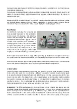
Once the engine is correctly installed and the components of the fuel system are fitted and con-
nected up, the ECU can be aligned to the radio system. This is a simple procedure which should be
done whenever your radio is programmed for a model, or the engine is new or returned from ser-
vice or repair.
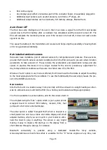
Radio Setup
Confirm you have connected the ECU signal input to the throttle channel on your receiver. Connect
the display to the Hub if using the “Lite” option. To navigate through the menus the two left but-
tons move up and down the menus, the two right buttons increase and decrease the value set.
There is no need to confirm any settings unless prompted, as changing a value automatically up-
dates it.
Connect the ECU battery and note the display screen illuminates. Remove all rates, mixes, and
throttle travel settings in the transmitter. Before doing any adjustment on the ECU, check that
your transmitter is sending the correct signal by checking the reading on the display.
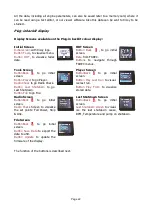
Press the 2
nd
button from left once to show an information screen.
Note at the top left there is a number showing the received radio sig-
nal shown as “Pulse = xxxxuS”. It should be between 900-1050uS at
STOP position, between 1100 and 1300uS at IDLE position and be-
tween 1800 and 2200uS at Full Power position. Ignore the % reading
to the top right for the moment. Please note that these readings are
measured directly from the signal received from your RC system, so
you should readjust your transmitter if the values read are outside that the ones suggested.
On some Futaba transmitters, it has been found that the throttle channel the sense of movement
may require reversing (servo reverse) and to repeat the transmitter alignment. The setting up as-
sumes the use of a transmitter (TX) with manual trims.
If you use a TX with digital trims, is essential to use the switch in the TX programmed
for the function "Throttle cut", or “engine cut” which normally has the effect of pro-


