Page 20
The ECU sends out a rpm request to the pump and receives actual rpm information and therefore
flow rate return signals back, and this process is updated continuously at high speed.
Please note, you must not try to run the pump by plugging this 3-wire cable into any brushless (3-
phase) driver, the controller will be immediately destroyed.
This system means the ECU does not have to spend time constantly controlling the pump speed, it
only needs to send a brief signal to request a certain rpm. The on-board controller then looks after
how this command is carried out and confirms it back when this is achieved. This enables the ECU
to do other things like updating telemetry or collecting data from sensors, while still controlling the
engine operation.
Pre-setting
The pump flow rate is set at the factory by setting the minimum rpm it produces sufficient heating
from the burner for a start on the engine. This is the only required adjustment. Once set, the user
needs make no adjustment to pump commands. We have made the increments 25 at a time as it
was found unnecessary to use any greater precision to achieve the desired result in a very small
range of numbers, usually 75, 100 or 125. Being based on a brushless motor it does not suffer
from sticky seals or variable speeds due to atmospherics or fuel densities unlike regular DC motor
based pumps. So the old juggle with adjustable “pump start point” is no more.
Applying a DC voltage to the fuel pump will not make it run so please do not try it. Modifying the
cable and reverse connecting the polarity of the power supply wires will also
not
make it run but
may destroy the internal pump controller, so don´t risk ruining your pump by modifying your cable,
just get the right length you need.
Mounting:
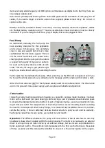
The fuel pump mounts using two M3 tapped holes in the body. Orientation is not criti-
cal but is ideally mounted with the pipes uppermost to minimise the possibility of trapped air bub-
bles.
Connection:
The pump direction of flow is marked with an engraved arrow from inlet to outlet.
The fuel pump inlet should have the fuel filter installed closely inline to prevent any particles get-
ting to the pump and jamming it. Use the piping supplied. The ring on the metal filter denotes the
outlet to go to the pump. Do not run the engine without a filter. The X45 and X90 use 4mm inlet
and outlet, the X120 has a 6mm inlet and 4mm outlet.
Bubble-Traps
A bubble-trap type hopper tank system is highly recommended and available in the
Xicoy web Shop. The bubble-trap outlet feeds direct to the inlet to the filter. If using an air trap
which has a fine bag type filter (Xicoy) then the external filter
CAN
be omitted but beware the
pump is vulnerable to particles getting in between bubble trap and pump inlet, so aim to be
squeaky clean with the installation. . If desired a shut-off tap can be installed inline as a protection
or where local regulations require.
The fuel outlet connects directly to the engine with 4mm piping. Do not connect anything (filters,
valves, fuel meters...etc.) between the pump and the engine.


