


25
2.0 INSTALLATION
©2000 Xantrex Technology Inc.
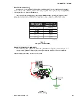
AC Wiring
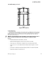
Sub-panel Mounting and Conduit Installation
NOTE: The installation of sub-panels and wiring should be performed by a qualified person or a
licensed electrician following all local and NEC codes.
Determine the location of the sub-panel and install it according to the manufacturers
directions.
Install the AC conduit between the sub-panel (output) and inverter.
WARNING: DISCONNECT THE POWER FROM THE UTILITYS MAIN BREAKER BOX BEFORE
PROCEEDING.
Install conduit between the inverter (input) and the main breaker box.
Determine which circuits require backup. Install the appropriate circuit breakers into the
sub-panel.
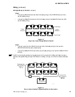
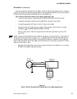
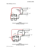
Install a 60 amp (disconnect) circuit breaker in the sub-panel. This will later be wired to the
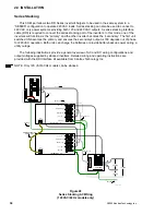
inverters output. If two inverters are being used in a stacked configuration, install two 60
amp circuit breakers for 240 VAC service (one in each leg of the circuit for L1 and L2).
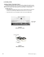
Input to the Inverter
CAUTION: THE INVERTERS AC OUTPUT MUST NEVER BE WIRED TO THE UTILITY OR
GENERATOR OUTPUT. THIS WILL CAUSE SEVERE DAMAGE TO THE INVERTER WHICH IS
NOT COVERED UNDER WARRANTY.
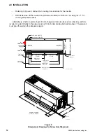
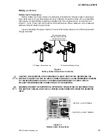
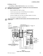
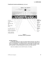
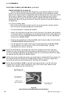
All AC wiring connects to the terminal block located on the right-hand side of the inverter.
To access the terminal block, remove the side cover panels (if installed) by removing the
two (or three) Phillips screws. Units are shipped without the covers installed (packed in a
small plastic bag with additional hardware).
Locate the AC input and output terminals on the block. Refer to Figure 23.
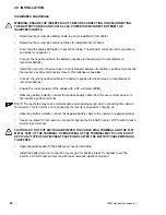
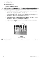
NOTE: The lower AC cover varies depending on the systems power level. Higher power units are
equipped with a conduit box and not a plate. The conduit box is required for the larger diameter
wire providing ample bending radius.
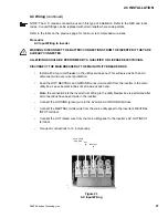
Figure 22
AC Wiring Access Cover Plates
Screws
High Power Conduit Box
Standard Cover Plate
Содержание Trace DR Series
Страница 1: ...Installation Operator s Manual DR Series Inverter Charger ...
Страница 2: ......
Страница 81: ......
Страница 82: ......
Страница 83: ......


