


22
Smart Pad
3
B A 9 8 7 6
5
4
3
2
1
0
F
E
D
C
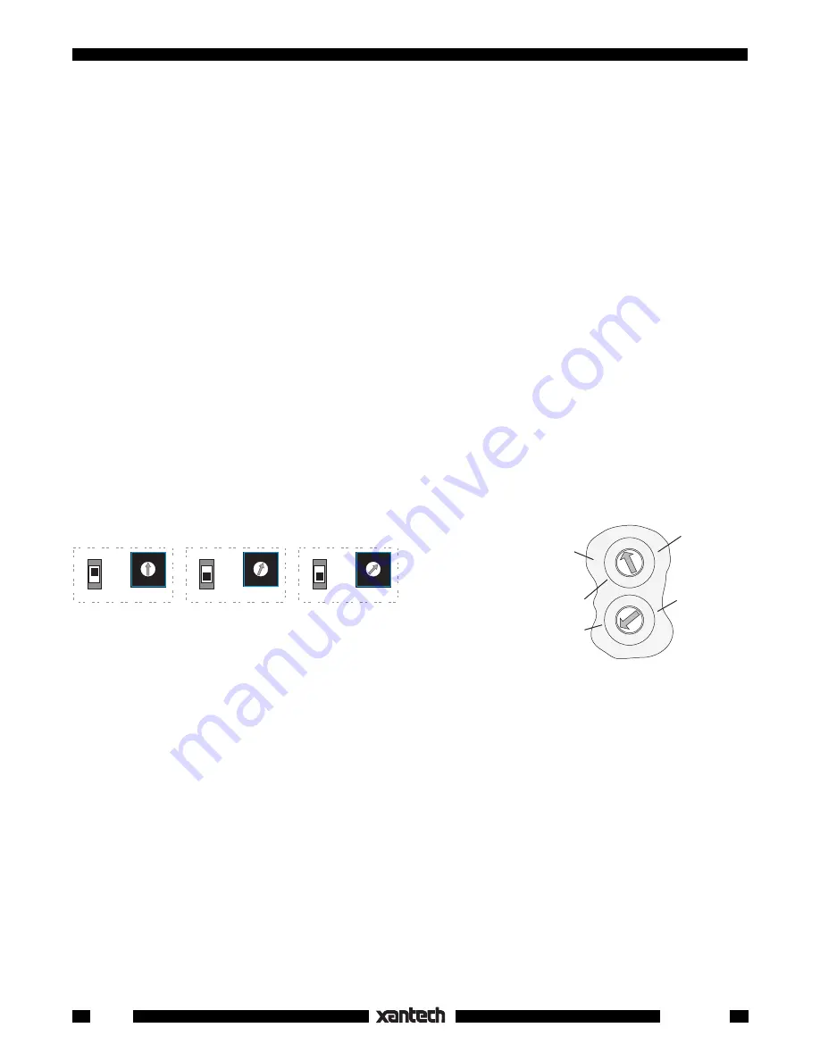
KEYPAD #1
(PM110)
Address 0
KEYPAD #2
(PM110 or LM110)
Address 1
KEYPAD #3, etc.
(PM110 or LM110)
Address 2, etc.
B A 9 8 7 6
5
4
3
2
1
0
F
E
D
C
B A 9 8 7 6
5
4
3
2
1
0
F
E
D
C
PROTECT
WRITE
PROTECT
WRITE
PROTECT
WRITE
NETWORK
ADDRESS
NETWORK
ADDRESS
NETWORK
ADDRESS
Fig. 25
Set Network Address & Write/Protect Switches
1st Digit
(Upper)
2nd Digit
(lower)
RC68
(rear
panel)
0 1 2
3
4
5
6
78
9A
B
C
D
E
F
0 1 2
3
4
5
6
78
9A
B
C
D
E
F
1st Digit
(Left on
RC68+,
Upper on
RC68)
2nd Digit
(Right on
RC68+,
Lower on
RC68)
Fig. 26
FB
Setting for
Bank Track Changes
1. Connect the keypads for the zone onto a common IR bus (network) along with an IR receiver as shown
in
Fig. 20
. Be sure the system is powered.
2. If you have not already done so, set each SmartPad
3
to a
unique NETWORK ADDRESS
such as 0,
1, 2, 3, etc. (
Fig. 21
).
3. Set the
WRITE/PROTECT
switch to
WRITE
on the 1st keypad (i.e., the keypad with Network Address
0) that you wish to change and press the
RESTORE
button.
4. On all the other keypads, set the
WRITE/PROTECT
switch to
PROTECT.
5. Set the rear switches on the back of the RC 68 or RC68+ to
FF
.
6. Direct the RC68 toward the IR receiver and press a key that reflects the desired Code Group.
CAUTION:
Do not choose a Code Group that is the same as other Xantech products that you may have
in the same IR system.
7. The active Source (bank) button and NETWORK LED's on the SmartPad
3
will flash once
indicating
that the change has taken place.
8. Repeat steps 3 through 7 for any additional keypads you wish to change.
The factory default value of
D8
can always be returned to by pressing D8 in the above process or by doing
a CLR MEM (
Fig. 15
). Be aware that CLR MEM will erase all user programming!
Bank Tracking Programming
Each Source (bank) key of the SmartPad
3
can be programmed to output one of up to 16 different Bank
Tracking commands. This is useful if you want a different arrangement of source buttons in one room
compared to another but still retain bank tracking between them, or to work more logically with the fixed
source keys of a handheld learning remote. To program different tracking commands, proceed as follows:
1. Connect the keypads for the zone onto a common IR bus (network) along with an IR receiver as shown
in
Fig. 20
. Be sure the system is powered.
2. If you have not already done so, set each SmartPad
3
to a
unique NETWORK ADDRESS
such as 0,
1, 2, 3, etc. See
Fig. 25
.
3. Set the
WRITE/PROTECT
switch to
WRITE
on the 1st keypad (i.e., the keypad with Network Address
0) that you wish to change and press the
RESTORE
button.
4. On all the other keypads, set the
WRITE/PROTECT
switch to
PROTECT
. See
Fig. 25
.
5. Next, press the Source (bank) key you wish to change.
6. Set the rear switches on the back of the RC 68 or RC68+ to
FB
per
Fig. 26
.
At this point, 16 default codes are available for rearrangement, if needed, labeled on the surface of the
buttons on the RC68 or RC68+ as 10 (80 on RC68+), 48, 01 (10 on RC68+), 90, 00, C0, 50, D0, 40,
A0, 30, B0, 20, E0, 70, & FO. See
Fig. 27
.
The first 8 relate, in left to right order, to the 2, 4, 6 & 8 banks currently available on the SmartPad
3
key
modules (KM2, KM4, KM6 & KM8). Refer to
Fig. 27
.
Use the first 8 when you want to make bank tracking changes so that source tracking will agree
between keypads with different source button arrangements.
Use the 2nd 8 if you want to bank track between certain keypads but not with the others.