background image

M U L T I - A N G L E   S P E C T R O P H O T O M E T E R  

17


Header Bar  

The header bar at the top displays the sample storage locations remaining, lamp configuration, 
measurement trigger method, USB connection, and battery gauge. 


Storage Capacity Indication

 - Displays the number of remaining sample storage 

locations. 


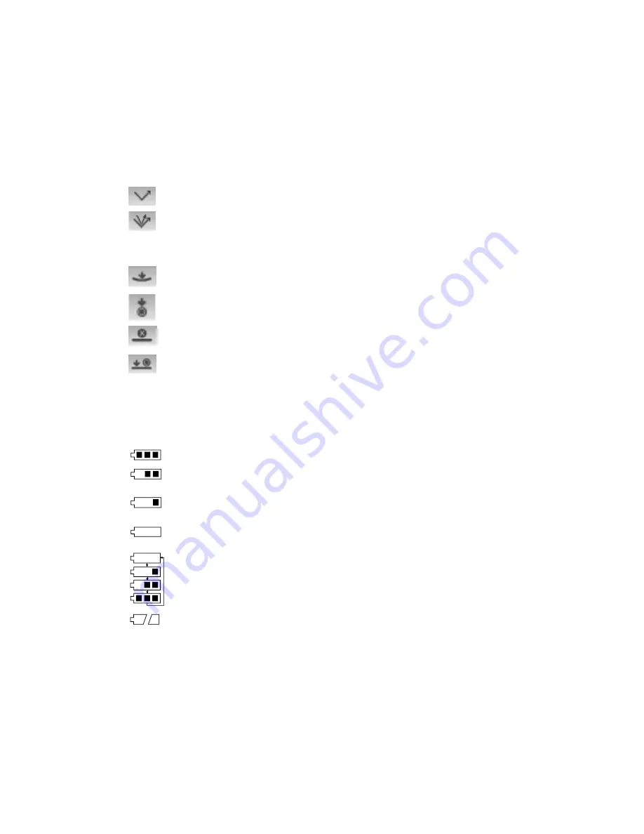
Lamp Indication (MA98 only)

 – Depicts the current lamp configuration. The lamp 

configuration is selected in the configuration mode. 


Indicates that the 45° lamp is currently in use. 


Indicates that both the 45° and 15° lamps are currently in use. 


Measurement Trigger Method

 - Depicts the measurement method currently selected 

for the instrument. 


Indicates the pressure sensors around the measurement port are active, 
requiring proper positioning to take a measurement. 


Indicates the measure button on the side of the instrument must be 
pressed to take a measurement. 


Indicates neither the sensors nor measure button will initiate a 
measurement. A software command is required to initiate a measurement. 


Indicates that both the pressure sensors and measure button are required 
to take a measurement. 


USB or Bluetooth Connection

 – The USB icon appears when the instrument is plugged 

into the USB port on the computer. The Bluetooth

®

 icon appears when searching for a 

connection and when a connection is established to the X-Color QC computer. 


Battery Gauge

 - Depicts the current condition of the battery pack. 


Indicates the battery pack is fully charged. 


Indicates the battery pack has a sufficient charge for a substantial number 
of measurements. 


Indicates the battery pack is low, but measurements are still possible. 
Battery pack should be charged soon. 


Indicates the battery pack is 

very

 low and only a few measurements 

remain. Battery pack should be charged immediately. 


Indicates the AC adapter is plugged in and the battery pack is charging 
(battery indication segments cycle). The battery indicator will stop cycling 
and display all segments when the battery pack is fully charged. 


Indicates that battery pack is removed and the instrument is operating 
from the AC adapter only. 

Main Column 

The main column is used to access the main instrument screen, wireless connection, and the 
configuration mode. 

View Column 

The view column lists any options that may be available for the selected mode. The highlighted 
option is the one that is currently displaying in the content area. 

Содержание MA94

Страница 1: ...Multi Angle Spectrophotometer Covers models MA94 MA96 and MA98 User Guide ...

Страница 2: ......

Страница 3: ...ntial area is likely to cause harmful interference in which case the user will be required to correct the interference at his own expense Industry Canada Compliance Statement This Class A digital apparatus complies with Canadian ICES 003 Cet appareil numérique de la classe A est conforme à la norme NMB 003 du Canada Equipment Information Use of this equipment in a manner other than that specified ...

Страница 4: ...N 301489 1 V1 9 2 2011 EN 301489 17 V2 2 1 2012 EN 60950 1 2006 ITE General Requirement EN 62479 2010 A11 2009 A1 2010 A12 2011 FCC RF Radiation Exposure Statement This device complies with FCC radiation exposure limits set forth for an uncontrolled environment End users must follow the specific operating instructions for satisfying RF exposure compliance This transmitter must not be co located or...

Страница 5: ... s accompanying documentation or published specifications iii repair or service by anyone other than X Rite or its authorized representatives iv the failure of the warranted goods caused by use of any parts or consumables not manufactured distributed or approved by X Rite v any attachments or modifications to the warranted goods that are not manufactured distributed or approved by X Rite Consumabl...

Страница 6: ...TION TO THE FOREGOING IN NO EVENT WILL X RITE BE LIABLE FOR ANY OF BUYER S MANUFACTURING COSTS OVERHEAD LOST PROFITS GOODWILL OTHER EXPENSES OR ANY INDIRECT SPECIAL INCIDENTAL OR CONSEQUENTIAL DAMAGES BASED UPON BREACH OF ANY WARRANTY BREACH OF CONTRACT NEGLIGENCE STRICT TORT OR ANY OTHER LEGAL THEORY IN ANY EVENT OF LIABILITY X RITE S MAXIMUM LIABILITY HEREUNDER WILL NOT EXCEED THE PRICE OF THE G...

Страница 7: ...s and Indicator LEDs 14 Instrument Positioning 15 Additional Tips 15 Main Screen Menu 16 Measure Mode 16 Job Mode 16 Calibration Mode 16 Configuration Mode 16 Wireless Mode 16 Display Screen Layout 16 Header Bar 17 Main Column 17 View Column 17 Content Area 18 Progress Column 18 Wireless Operation 18 Configuration Mode 19 Entering Configuration Mode 19 Lamp Selection MA98 only 20 Measurement Trigg...

Страница 8: ...ombinations 31 Measuring a Sample 32 Using Measurement Averaging 33 Using Graph View 34 Viewing Stored Measurements 35 Viewing Pass Fail Data 35 L a b Color Space pass fail 35 L a b Color Space pass warning 36 Pass Fail Option 36 Using Quick Compare 37 Creating Standards 38 Job Mode 39 Accessing Job Mode 39 Job Mode Icons 39 Selecting and Running a Job 40 Appendices 42 Service Information 42 Clean...

Страница 9: ...d on the bottom of the instrument to aid in proper positioning How to Use this Manual This manual is intended to provide setup operation and general maintenance of the instrument Specific software application information is available in the software help system Packaging Your instrument packaging should contain all the items listed below If any of these items are missing or damaged contact X Rite ...

Страница 10: ...ry contacts facing down 3 Release the latch and close the access cover by pressing downward until it locks into position Use the rechargeable Li ion batteries provided or equivalent other types may burst causing personal injury Turning the Instrument On and Off The power button is used to initiate the instrument from a power off state Simply press and hold the button for three seconds to turn on t...

Страница 11: ... for full charge A charged battery pack may eventually lose partial charge if not used for an extended amount of time You should charge the battery from time to time and store in a cool environment when not in use to maintain battery performance The battery pack can be charged in the instrument see Connecting the AC Adapter or by use of the charging station The charging station is useful for charg...

Страница 12: ...pter and plug the line cord into the wall receptacle 3 Position a battery pack over one of the charging locations with the locking tabs in the station directly below the slots in the battery Make sure the arrow on the top of the battery pack is facing the LED end of the station 4 Lower the battery pack into position and slide it toward the LED until it stops Depending on the battery packs current ...

Страница 13: ...eptacle Connecting the USB Cable IMPORTANT You must install the software before connecting the instrument to your computer 1 Install the software application if not already installed Refer to the software documentation for additional information 2 Remove the small access cover that is located above the AC adapter and USB inputs 3 Turn the instrument on and plug the square end of the USB cable into...

Страница 14: ...of the instrument 2 Insert the wrist strap end through the small loop 3 Pull on the wrist strap to secure to the strap pin 4 Use the slide to tighten the strap around your wrist Attaching the Dust Cover The dust cover protects the measurement port and internal optics components Make sure the instrument is always stored with the cover installed 1 Position the cover in either direction below the mea...

Страница 15: ... down buttons perform the same function only in an up and down direction The navigation buttons change control direction when the instrument screen orientation is changed from right handed operation default to left handed operation in the Configuration Mode Select Button The Select button activates the control that has focus such as a mode or option Measure Button The Measure button is located on ...

Страница 16: ...ttern as the pressure sensors located in the measurement port Refer below for LED definitions NOTE The Pressure sensor option must be enabled in Configuration mode LED Off little or no pressure is being applied to the corresponding sensor LED Amber not enough force is being applied to the corresponding sensor You must apply additional pressure to achieve a green LED LED Green ideal pressure is bei...

Страница 17: ...l all three indicator LEDs turn green Additional Tips Measurements performed on a surface with a curve can cause measurement errors especially at the near specular angles 15 and 25 Measurements should be made on the flattest part of a sample whenever possible When measuring parts where a flat area is not available a fixture should be made to repeatedly and accurately position the sample tangent to...

Страница 18: ...nformation Calibration Mode The calibration mode is use to perform a black and white reference calibration Refer to the Calibration Mode section for information Configuration Mode The configuration mode is used to set and edit the instruments configuration options The configuration options should be set before you use your instrument for the first time Refer to the Configuration Mode section for i...

Страница 19: ...a measurement USB or Bluetooth Connection The USB icon appears when the instrument is plugged into the USB port on the computer The Bluetooth icon appears when searching for a connection and when a connection is established to the X Color QC computer Battery Gauge Depicts the current condition of the battery pack Indicates the battery pack is fully charged Indicates the battery pack has a sufficie...

Страница 20: ...e that follows to pair your instrument to the computer Pairing Procedure 1 Make sure the USB cable is not connected to the instrument 2 Use the Navigation buttons to move the highlight focus to the Bluetooth icon in the Main column USB must be disconnected 3 Press the Select button to put the instrument into discoverable mode The instrument will stay in discoverable mode for up to 60 seconds If a ...

Страница 21: ...tion model serial number and firmware 3 From the Configuration screen use the Up or Down navigation buttons to move the highlight focus to the desired configuration icon in the Options column NOTE The arrow icon or at the end of the Options column indicates that additional options are available Move the highlight focus to the arrow icon and press the Select button to access the additional options ...

Страница 22: ... sensors are required to take a measurement Button Measure button is required to take a measurement Software Only No button or pressure sensors are required to take a measurement This setting would be selected when software input is used to trigger a measurement Pressure and Button Both the pressure sensors and measure button are required to a take a measurement Pressure Sensor Sensitivity This op...

Страница 23: ...ier free measurements are achieved or the sample is determined too variable Calibration Timeout This option is used to set the amount of time that elapses before a calibration is required The available settings are Disabled 8 Hours 12 Hours 24 hours default 48 Hours and 1 Week Sample Storage This option is used to enable or disable default the storage of samples in the instrument Enabled Sample st...

Страница 24: ...inant Observers This option is used to select the allowed illuminant observer combinations that appear in the Measure Mode You can select as many illumination observers as desired An arrow appears next to the selected illuminant observer combinations Language This option is used to set the language that is displayed on the instrument The available settings are English default German French Spanish...

Страница 25: ...s of inactivity Short The instrument goes into standby mode after 1 minute and shuts completely off after 2 minutes of inactivity Instrument Orientation This option is used to change the display direction to accommodate both right and left handed users The available settings are Right Handed default and Left Handed Clear All Samples This option is used to clear all samples stored in the instrument...

Страница 26: ...optics cleaning procedure The white plaque in the calibration reference is dramatically affected by smudge marks dust and finger prints Refer to Appendices for calibration reference cleaning procedures The black trap should be cleaned periodically to remove any dust or contamination Refer to Appendices for black trap cleaning procedures Do not move instrument while taking a calibration measurement...

Страница 27: ...ument Calibrating the Instrument 1 From the Main screen use the Navigation buttons to move the highlight square to the Calibration icon 2 Press the Select button to access the calibration screen White Calibration Expired appears if calibration is needed If calibration is not currently needed the time remaining before the next calibration along with the temperature of the last calibration and white...

Страница 28: ... clear the message and try measuring the black trap again If an error still occurs clean the black trap as explained in the Appendices 5 Position the instrument on the white reference as previously explained and press the Select button Take the measurement s by applying the appropriate amount of pressure to the port to activate the pressure sensors green indicator LEDs Hold the instrument steady t...

Страница 29: ...elect button to access the main measure screen Measure Mode Icons A description of the various icons found in the measure mode is shown below Icon Description Access the main measurement screen Access color space selection screen Arrow points to current color space selected Access illuminant observer selection screen Arrow points to current illum obs selected Access group detail and selection scre...

Страница 30: ...led sample measurement Selecting a Group The group option lists grouped standards that were created and downloaded from the X Color QC application When multiple standard groups are available you must select the desired group before taking a measurement when using auto standard The auto standard select function does not recognize standards across multiple groups The selected group is used until a d...

Страница 31: ...utomatically chooses the closest standard to the measured sample In manual select mode you must choose the standard before a measurement The manually selected standard is used until a different standard is chosen To select a standard 1 From the Measure screen use the Up or Down navigation buttons to move the highlight focus to the Standard icon 2 Press the Right navigation button to access the sta...

Страница 32: ...ghted to change to the next allowed color space Color Spaces L a b default L a b E default Eeff E94 DNA10 F19 SI L C h default L C H Ecmc Ec F10 SI G19 IL Flop Index Flop Index Ep E00 G10 default IL DNA19 MA98 only NOTE Delta color spaces will not appear if no standard is selected Certain color spaces may not appear if they are not allowed in the Configuration mode To select a color space 1 From t...

Страница 33: ...ombinations may not appear if they are not allowed in the Configuration mode To select illuminant observer combinations 1 From the Measure screen use the Up or Down navigation buttons to move the highlight focus to the Illuminant Observer icon 2 Press the Right navigation button to access the illuminant observer selection area 3 Use the Up or Down navigation buttons to move the highlight focus to ...

Страница 34: ...n 5 If averaging is used reposition the instrument on the sample and take additional measurements Refer to Using Measurement Averaging later in this section for information 6 View measurement results on the display NOTE If an error occurs during a measurement try measuring the sample again If the error still occurs refer to the Troubleshooting section in the Appendices Measure icon You can delete ...

Страница 35: ...he Measure screen use the Up or Down navigation buttons to move the highlight focus to the View column and then to the Measure icon 3 Position the instrument on the first area of the sample and take a measurement After the measurement the instrument displays Averaged 1 of 2 in the screen indicating one more measurement is required for results Note When averaging using SMC a cancel icon appears in ...

Страница 36: ...tion buttons to highlight the Graph View icon and press Select Note The Graph icon will not appear in the Progress column unless one of the delta color spaces listed above is first selected 3 With the Content area highlight use the Up or Down navigation buttons to page through a graph view for each angle 4 To exit the graph view highlight the Graph View icon and press Select The screen returns bac...

Страница 37: ...o highlight the or icon and press Select Each time Select is pressed the screen displays the next or previous store measurement Viewing Pass Fail Data A red or green bar displays for any aspecular standard angle that has a tolerances set Angles that have no tolerance set will remain gray in color Refer to X Rite s X Color QC software application for information on setting tolerancing for standards...

Страница 38: ...ce group gives you a quick pass fail view of a sample Select the X option to activate the pass fail display screen This example shows the 15 angle highlighted in red and the 45 angle highlighted in green indicating the 15 angle failed The X and red bar indicate that at least one angle failed tolerance Failed Passed Failed Example Pass Warning Example Passed with Warning This example shows the 15 a...

Страница 39: ...easure screen use the Right navigation button to move the highlight focus to the Progress column 3 Use the Up or Down navigation buttons to highlight the Quick Compare icon and press Select A small x appears next to the Compare icon and Quick Compare appears in the header bar The Content Area will change to the delta color space of the last selected color space before the comparison measurement 4 ...

Страница 40: ...the instrument To create a standard 1 From the Measure screen use the Right navigation button to move the highlight focus to the Progress column 2 Use the Up or Down navigation buttons to highlight the or icon and press the Select button to find the sample you want to use as a standard 3 After the desired sample is displayed use the Navigation buttons to move the highlight focus back to the View c...

Страница 41: ...he instrument and uploading job data to the software application Accessing Job Mode 1 From the Main screen use the Navigation buttons to move the highlight square to the Job icon 2 Press the Select button to access the main job screen Job Mode Icons A description of the various icons found in the job mode is shown below Icon Description Access the main job screen Used to view the steps of the sele...

Страница 42: ...b 2 Use the Right navigation button to move the highlight focus to the Progress column Use the Down navigation button to highlight the Next arrow icon if not selected and press the Select button to open the job The first step in the job sequence is displayed 3 Make sure the Next arrow icon is selected and press the Select button 4 Position the instrument on the sample as described on the screen an...

Страница 43: ... 6 Position the instrument on the sample as described on the screen and take the measurement 7 Data appears on the display for the second measurement 8 The job is now completed Make sure the Next arrow icon is selected and press the Select button to return to the main job screen 1st measurement data Next arrow icon 3rd step measurement instruction with graphic 2nd measurement data ...

Страница 44: ...round the world You can contact us using one of the following methods To identify the X Rite service center nearest you please visit our web site at www xrite com and click the Contact Us link For online help visit our web site and click the Support link Here you can search for software or firmware updates white papers or frequently asked questions which can quickly resolve many common user proble...

Страница 45: ... The optics should be cleaned once a week in a normal environment If the instrument is used in a dirty or dusty environment more frequent cleaning may be required Carefully lift the instrument and blow short bursts of clean dry air into the measurement port This should remove any accumulated debris from the optics IMPORTANT If can air is used for cleaning do not invert or tilt the can during use T...

Страница 46: ... batteries provided or equivalent other types may burst causing personal injury 1 Carefully turn the instrument over and slide the latch that secures the battery pack access cover towards the front of the instrument Open the access cover 2 While holding the latch open turn instrument over allowing old battery back to slide out 3 Insert the new battery pack into the instrument with the battery cont...

Страница 47: ... cleaning Refer to Optics cleaning procedure in Appendix for procedure Instrument requires calibration Refer to Calibration mode for procedure Calibration procedure fails Calibration reference is dirty or damaged Clean the reference per procedure in Appendix or replace if damaged Instrument and software not communicating USB connection Interface cable not connected Connect the interface cable betw...

Страница 48: ...ific condition If an error condition persists please contact our technical support using one of the methods listed in the Service Information section Resetting the Instrument To reset the instrument 1 Unplug the interface cable and AC adapter from the instrument if connected 2 Open the battery access cover and remove the battery 3 Reinstall the battery and power up the instrument If you are still ...

Страница 49: ...measured points Measurement Range 0 400 Colorimetric Illuminants A C D50 D65 F2 F7 F11 and F12 Colorimetric Standard Observers 2 10 Colorimetric Scales L a b L C h E ECMC E DIN6175 E2000 Effect Parameters xDNA Flop Index Measurement Time Approx 2 seconds Reproducibility 0 18 ΔE avg on reference Series II BCRA tile set Inter instrument agreement Repeatability 0 03 E on white cal plaque 20 measureme...

Страница 50: ...Humidity Max 85 RH max non condensing Storage Temp 4 F to 122 F 20 C to 50 C Usage Indoor Only Altitude 2000m Pollution Degree 2 Transient Overvoltage Category II Standards ASTM D 2244 E 308 E 1164 E 2194 E 2539 MA98 DIN 5033 6174 6175 2 ISO 7724 SAE J1545 Design and specifications subject to change without notice ...

Страница 51: ......

Страница 52: ......

Страница 53: ...eadquarters X Rite Europe GmbH Althardstrasse 70 8105 Regensdorf Switzerland Phone 41 44 842 24 00 Fax 41 44 842 22 22 Asia Pacific Headquarters X Rite Asia Pacific Limited Suite 2801 28th Floor AXA Tower Landmark East 100 How Ming Street Kwun Tong Kowloon Hong Kong Phone 852 2568 6283 Fax 852 2885 8610 Please visit www xrite com for a local office near you P N MA98 500 Rev I ...

Отзывы: