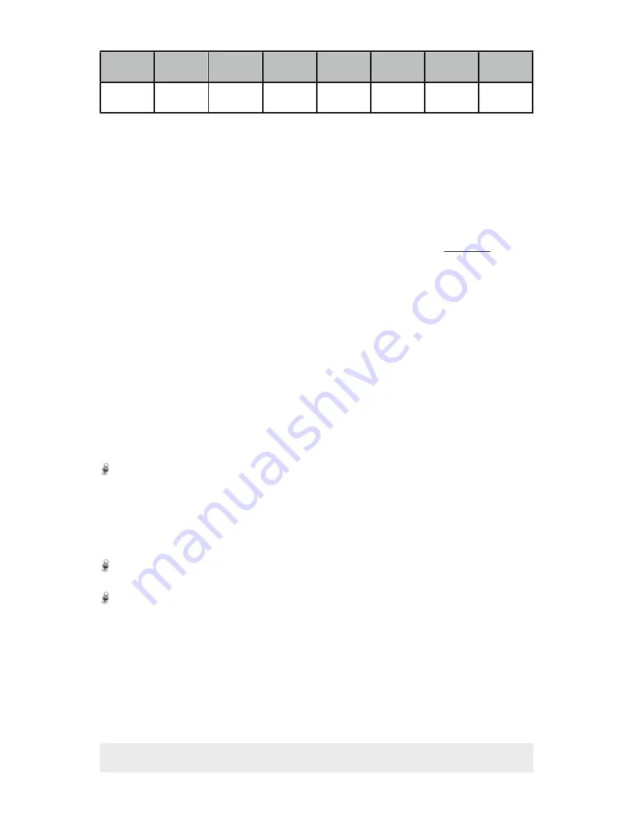
Pod 1
Pod 2
Pod 3
Pod 4
Pod 5
Pod 6
Pod 7
Pod 8
+1
+2
+4
+8
+16
+32
+64
+128
Using the example from before:
If you want heads 1, 2, 6, and 8 on and heads 3, 4, 5 and 7 off, you use
the table above to look up numbers for heads 1, 2, 6 and 8 and add them
together. The resulting calculation would be 1 + 2 + 32 + 128 (head 1,
head 2, head 6, head 8) = 163. This is the Channel 2 DMX value you
would use if you wanted heads 1, 2, 6, and 8 on and heads 3, 4, 5, and 7
off. A full chart is available on the X-Laser
®
website under Support.
Please note that you MUST be using a DMX controller capable of abso-
lute value (0-255) DMX programming as opposed to some consoles
which only use DMX in percentage (0-100%). While X-Pod
®
will still work
with a percentage-based DMX controller some effects will likely not work
properly.
Creating a DMX Circuit
Your X-Laser
®
product can be linked to other X-Laser
®
fixtures or other
DMX compatible fixtures. To create this link, it is recommended that true
DMX cable be used for best operation and that the DMX chain be termi-
nated at the end of the link. Please follow these steps:
From your DMX controller, connect a 3 pin DMX cable to the “DMX IN”
port on the back of your X-Laser
®
product. For any additional fixtures,
continue to daisy chain the DMX cable from the “DMX OUT” port on
the first fixture to the “DMX IN” port on the next fixture and so forth
down the line. Your total length of DMX cable should not exceed 300
feet;
At the end of the DMX link, place a DMX terminator into the “DMX
OUT” port of the last fixture in the link;
Use the dip switches (explained above) to set the DMX address of
each fixture in the chain.
Page 14
of 18


