background image

8

Technical support: [email protected]     EMEA/ROW: +44 (0) 1793 230 343

US/CAN/MEX: +1-518-289-1294     Toll Free Technical Support: +1-844-280-WYRE (9973)

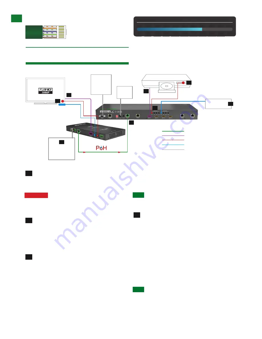
        Connect HDMI sources (such as HD-DVD, Blu-ray, 

games console, AppleTV, satellite/cable etc.) to HDMI 

inputs 1 – 4 of the MATRIX. 

Attention

  Do Not Hotplug! - Please insert and 

extract cables carefully with the power SWITCHED 

OFF.  Connecting and disconnecting while the unit is 

powered can result in damage to circuitry.

        Attach the IR emitter directly over the infrared 

receiving sensor of the input source using the adhesive 

backing. You may need to adjust the position of the 

emitter after installation to achieve the best results. 

Sometimes moving the sensor to different areas of the 

source can improve IR performance.

        Plug the 3.5mm jack of the IR emitter into your 

chosen number IR TX port on the rear panel of the 

MATRIX.

For two-way IR control of the display from the matrix or 

connection to a control system, connect an IR Link cable 

to the control system or plug an IR RX receiver cable into 

the corresponding IR RX port on the rear panel of the 

MATRIX, ensuring the receiver is placed in clear view to 

receive an IR signal. 

NOTE

 Make sure the IR jacks are in the same number 

ports.

HINT  

Locate the infrared sensor on devices by 

shining a flashlight onto the display panel of sources 

and look for a small sensor.


        Connect a good quality, well terminated Cat5e/6 

cable with an RJ45 connector wired to 568B standard 

at both ends from the UTP Output port of the MATRIX to 

the UTP In of the display receiver.  If cascading an output, 

connect the UTP to the UTP IN of the transmission 

device.

Ensure both RJ45 connectors are pushed securely into 

each port and supported by the connector strain relief 

clip to prevent them from becoming loose. The quality 

of termination for your RJ45 is essential. Poor quality 

terminations lead to intermittent performance and longer 

install times.

HINT


Although all WyreStorm products are tested 

using Cat5e as standard, we suggest using Cat6 as 

the preferred cable due to its improved distribution 

capabilities.

1

2

3

4

CONNECTION

8.     Connection

Key

cat 5

e

/6

hdmi

rs232

ir tx

ir rx

HDMI Source

display 1

Control 

System 

(additional 

control 

via 

RS232)

IR TX emitter placed directly 

over device IR window.

IR RX LINK Cable 

connecting from Control 

System to IR RX port of 

matrix

IR TX emitter placed directly 

over device IR window.  IR 

RX receiver placed discretely 

on or near display device with 

clear line of sight to remote 

handset being used

Additional 12v 

mains power 

connection

(Optional)

24v DC

Power

Control

System

Cat5e/6 Wiring Guide

The quality of termination for every RJ45 is essential. Poor terminations  


leads to intermittent performance and  

   longer 

install 

times.

Cat5e/6 Cable


Performance Guide

MX-0404-POH-KIT

0ft

328ft

32ft

65ft

98ft 131ft 164ft 197ft 230ft 262ft 295ft

0m

100m

10m

20m 30m

40m 50m

60m 70m

80m 90m

1

2

3

3

4

6

5

7

Содержание MX-0404-POH-KIT

Страница 1: ...D Matrix with 4 x 70m HDBaseT PoH HD Display Receivers Thank you for choosing this WyreStorm product Please read these instructions carefully before installing to avoid complications later Instruction...

Страница 2: ...ter flexibility and convenience during installation as well as improved energy efficiency compared to a permanent mains connection The system offers flexibility and reliability of signal distribution...

Страница 3: ...ned into a universal remote handset to allow the control of multiple devices from one handset 4 x IR 3 5mm mini jack ports for each output 4 x IR 3 5mm mini jack ports for each source Additional infra...

Страница 4: ...HNICAL I O Connections MATRIX 4 x HDMI IN 4 x HDBaseT OUT 1 x RS232 1 x IR EXT 1 x EDID DIP switch RECEIVER 1 x HDBaseT IN 1 x HDMI OUT Output Signal Type HDMI1 3 with HDCP Output Bandwidth Signalling...

Страница 5: ...nd no patch panels or wall outlets used The presence of any of these factors may compromise bandwidth and signal strength Cable Type Range Supported Video HDMI 1 3 Cat5e 6 Cat56a 7 15m 49ft 70m 230ft...

Страница 6: ...ate mode used to update the firmware of the receiver Note When used with the MX 0404 POH KIT the RS232 port can only be used for firmware update serial control of the receiver itself is not possible P...

Страница 7: ...o display device IR RX Connects to IR receiver positioned near display device to enable control of source from display location IR TX Connects to IR emitter to display device to enable control of sour...

Страница 8: ...ed Cat5e 6 cable with an RJ45 connector wired to 568B standard at both ends from the UTP Output port of the MATRIX to the UTP In of the display receiver If cascading an output connect the UTP to the U...

Страница 9: ...ixed firmly in place behind the display Display receivers are powered remotely from the matrix so no mains power is required In instances where cable quality length or placement impacts on successful...

Страница 10: ...iple HDMI signals to multiple HDMI receivers located remotely it also passes IR control signals through the IR call back system to the matrix and HDMI sources for full independent control of all conne...

Страница 11: ...1 Input2 TX2 etc with plugs secured in correct ports and secondly that the IR emitter sensors are firmly attached directly to the front of inputs and covering infrared sensor windows of the source dev...

Страница 12: ...sen or problems with device communication through the matrix encountered basic operation is all that is required to operate your MX 0404 POH KIT However the following information on advanced operation...

Страница 13: ...connected to COM CTL The firmware version and creation date will be displayed together with the normal output state of the matrix Set IP button non functional To set your IP please refer to Smart Set...

Страница 14: ...er connection and a cross over cable for connection to a PC Using the incorrect cable will not damage your equipment but it may result in poor no connection Make sure that your LAN cable is correctly...

Страница 15: ...matrix EDID Copy from Output display to Input port Force Signal Output mode To copy the EDID from an OUTPUT display to a specific INPUT port first set the DIP switch to this position Then select the I...

Страница 16: ...oject requirements and is well within the maximum transmission distance of the signal Note If approaching the limits of the transmission capabilities transmission should be extended by using another e...

Страница 17: ...ld lie with the input or output device rather than the means of distribution i e the display rather than cable matrix or receiver itself 13 HDMI lead condition and quality HDMI cables and connectors a...

Страница 18: ...um of 1080p 60Hz Higher resolutions available for graphics based systems require higher bandwidth that may affect transmission of signals as well as incompatibility with devices IR 1 Check you are usi...

Страница 19: ...ame sequential 3D Blu ray but will still pass through interlaced stereoscopic 3D Satellite etc How do I control the sources All of our HDMI distribution products support IR pass through from point to...

Страница 20: ...ng section for more tips on problem solving Clean this unit with a soft dry cloth only Never use alcohol paint thinner or other harsh chemicals Provided Service 1 Damage requiring service This unit sh...

Страница 21: ...e power line surge lightening damage modification service by anyone other than a manufacturer approved service centre or factory authorised personnel or damage attributable to acts of God 2 There are...

Страница 22: ...EMEA ROW 44 0 1793 230 343 INSTALLATION NOTES INPUT Input number on Matrix Source Location Source Details Source resolution audio settings Cable Number 1 2 3 4 WyreStorm MX 0404 POH KIT Installation...

Страница 23: ...e Technical Support 1 844 280 WYRE 9973 INSTALLATION NOTES OUTPUT Output number on Matrix Output Location Display Details Display Resolution Audio Settings Cable Number 1 2 3 4 WyreStorm MX 0404 POH K...

Страница 24: ...Swindon Wiltshire SN3 3JW UK Tel 44 0 1793 230 343 WyreStorm Technical Support US 1 844 280 WYRE 9973 UK 44 0 1793 230 343 Email support wyrestorm com WyreStorm Technologies reserve the right to chan...

Отзывы: