background image

16

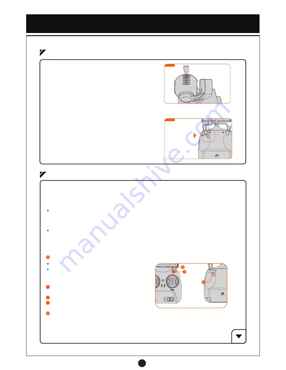
Gimbal Control Joystick

Figure 2

The 3-axis stabilized gimbal provides a steady mobile platform for the integrated HD camera.

Gimbal & Camera

(1) Camera Memory Card

The camera stores high definition pictures and videos 
to an installed memory card, the camera supports a 
memory card size up to 64GB. A memory card over 8GB 
and Class 10 is recommended for best performance. 
Install the memory card as shown (Figure 1.)

(3) Camera Operation

Toggle the R1 switch to the Down Position, flip the R2 switch
once to take a single photo.

Toggle the R1 switch to the Up Position, flip R2 switch once
to start recording video.

Flip R2 switch again to stop recording. 

(2) Gimbal Operation

The gimbal joystick is located on the back of the transmitter and controls the 2-axis (Up/Down & Left/Right)
movements of the camera (Figure 2). Each axis moves within a 90 degree radius.

4-1  Gimbal and Camera Operation

Figure 1

Figure 1

4-2  Camera Settings

Camera Mode Switch

Settings Interface Navigation

2

2

2

Gimbal Joystick 

Control

 Switch R2

 Switch R1

(2) Camera Settings Via Transmitter and Live Feed Screen

R1 Up Position: Record Video Mode
R1 Down Position: Photo Capture Mode 

Move Gimbal Joystick Up / Down: Select Submenu

Move Gimbal Joystick Right: Enter Submenu Options
Move Gimbal Joystick Left: Back / Toggle Menus

Toggle R2 switch: Select Button

Video Settings

(1) Choosing Video or Photo Settings

Enter Video Record Mode settings via toggling the R1 switch from the R1 Up Position to R1 Middle Position.
The gimbal joystick is used to choose menu options and settings while using R2 switch to confirm.

Photo Settings

Enter Photo Capture Mode settings via toggling the R1 switch from the R1 Down Position to R1 Middle Position.
The gimbal joystick is used to choose menu options and settings while using R2 switch to confirm.

Photo and Video settings are changed separately and depend on what mode you toggle from.

Содержание raptor

Страница 1: ......

Страница 2: ...down before picking up or handling DANGER Support Service Thank you for purchasing the World Tech Elite Raptor Live Feed Camera Drone This kit contains advanced equipment that connects to both WiFi signals and GPS Satellites Please read through the manual thoroughly to understand your new drones many functions Adhere to all local and federal laws regarding piloting Drones and other Unmanned Aircra...

Страница 3: ...ansmitter Battery 8 2 1 Drone Status Indicators 9 2 2 Flight Modes 9 3 1 Transmitter Operations 10 3 2 Live Feed Screen 15 4 1 Gimbal and Camera Operation 16 5 FLIGHT 18 6 ASSISTANT SOFTWARE 20 5 1 Flight Notes 18 5 2 Check and Calibrate the Compass 18 5 3 Flight Operation 19 6 1 Software Download and Firmware Upgrades 20 6 2 Software Functions 20 4 2 Camera Settings 17 ...

Страница 4: ...se visit worldtechtoys com to download the latest version for reference 8 For the best flying experience only use genuine World Tech Elite accessories 9 Remove all rotor blades before calibrating or changing parameter settings 10 Adhere to all local laws and rules in your area before flying you are solely responsible for all conduct and actions while you are flying 11 Check all connections Check r...

Страница 5: ...not drop or strike the drone battery pack Do not use a swollen leaky or damaged battery pack 6 If a battery pack leak is found do not make contact with skin or eyes If contact occurs immediately rinse with plenty of water and seek medical attention 7 The battery pack charge may be affected when used in low or high temperature environments 8 Dispose of batteries in accordance with local regulations...

Страница 6: ...Body GPS Status Indicator Blue LED Rotor Motor Orange LED Indicator Green LED Indicator Drone Battery Gimbal Assistant Port Power Buttons Battery Level Indicator Image Transmitter 3 Axis Gimbal Landing Skid Rubber Pads Landing Skids Integrated Camera Memory Card Slot ...

Страница 7: ...ment Cover Power Button Power Switch Right Stick Neck Strap Attachment Power Indicator Live Feed Screen Antenna Screen Bracket Side Locking Screw Screen Holder Lock Button Gimbal Joystick Sunscreen Shade Video Output Charging Port Screen Power Indicator Channel Selector FRONT BACK Trimming Buttons T1 T4 Left Stick L1 R1 R2 L2 Transmitter Handle T1 T4 T3 T2 ...

Страница 8: ... side locking screw 2 positioning the holder so it is secure before locking in the Live Feed Screen Warning Damaged rotors should only be replaced with official World Tech Elite Raptor Live Feed Camera Drone Rotors Please use the original World Tech Elite rotors only Please use the rotor wrench to remove and secure rotor nuts Ensure that all rotors are installed correctly and secure before every f...

Страница 9: ...shing Battery Error The battery pack should be charged in an ambient temperature of 32 F to 104 F Notice The battery packs temperature may be too high after flying Do not charge the battery immediately Charge battery when at room temperature Notice The Raptor Battery Pack is designed specifically for this drone and has a built in battery level indicator to easily check battery levels before and du...

Страница 10: ...gnal is less than 5 The drone will keep its altitude when hovering Stabilized Smooth GPS Mode GPS signal is greater than or equal to 5 Drone will keep position and altitude when hovering L1 to Middle Position L2 to Middle Position 2 Easy Mode Toggle L2 to the Down Position to activate Easy Mode when you cannot make out the front of the drone During this mode the directional controls simplify so th...

Страница 11: ...nd land as long as the GPS signal is greater than 5 The drone will maintain its current height when returning home if the drones height is higher than 65 feet If the drones height is lower than 65 feet it will ascend to 65 feet return home and land Controls are disabled while this mode is in effect toggle L1 to middle position if you need to use the controls to avoid obstacles or regain manual con...

Страница 12: ... Mode Function Switch 3 Position Switch R1 Middle Position Camera Setting Mode R1 Down Position Capture Photo Mode R1 Up Position Recording Video Mode R2 Switch 5 R2 Camera Mode Function Switch Toggle Switch Toggle R1 switch to the Down Position flip R2 switch once to take a single photo Toggle R1 switch to the Up Position flip R2 switch once to begin recording video Flip R2 switch again to stop r...

Страница 13: ...when calibrating via the software Land the drone when you are adjusting the trim After finished adjusting test drone by taking off to see results Repeat trim process until you have the ideal result Warning Lock the Trimming Buttons when finished adjusting the trim to avoid any accidental changes Warning Calibrating the trim via software is the recommended method of calibration Only use the trimmin...

Страница 14: ...switches when the Transmitter indicator blinks 6 Transmitter indicator stops flash and lighting stays solid 7 This indicates that the link has been successfully established 7 Power on the drone 7 Figure 2 Remove the rotors when re establishing the link 9 How to Operate the Transmitter The Mode 1 and Mode 2 of the transmitter can be changed through Trimming Button For Basic Flight Operations see be...

Страница 15: ... Calibration Mode Turn the drone off Press the 4 trim buttons simultaneously Figure 1 The mode has switched when you hear a beep sound One beep indicates Mode 1 Two beeps indicates mode 2 Turn on the transmitter Trimming Mode should be locked Use the software to calibrate the drone and transmitter after switching modes Notice Sound Indicators Powering on the transmitter One beep when turning on Lo...

Страница 16: ...plays a red LED to show the charging status the battery is fully charged when the LED turns green Live Feed Screen charge time is approximately 4 hours 4 Switch Video Feed Channel If the Live Feed Screen has interference or a fuzzy picture you can change the screen between 8 different channels to get the best quality feed Change the channel as shown below Channel 1 is the factory default for the L...

Страница 17: ...ree radius 4 1 Gimbal and Camera Operation Figure 1 Figure 1 4 2 Camera Settings Camera Mode Switch Settings Interface Navigation 2 2 2 Gimbal Joystick Control Switch R2 Switch R1 2 Camera Settings Via Transmitter and Live Feed Screen R1 Up Position Record Video Mode R1 Down Position Photo Capture Mode Move Gimbal Joystick Up Down Select Submenu Move Gimbal Joystick Right Enter Submenu Options Mov...

Страница 18: ...erent megapixel resolutions you want your photos taken in Sequence Toggle sequential numbering of image files on or off Quality Change the photo quality between Fine Normal and Economy The better the quality the larger the file size Sharpness Choose between Strong Normal and Soft photo sharpness White Balance Depending on lighting choose between Auto Daylight Cloudy Tungsten and Fluorescent option...

Страница 19: ...ating the Compass Make sure to calibrate the drones compass when you fly for the first time or at a new location After powering on the transmitter and drone rapidly flip the L1 switch from the up to the down position at least 5 times until the 4 LED indicators underneath the drone starts slowly flashing indicating compass calibration mode initiating Holding the drone horizontally rotate the drone ...

Страница 20: ... to control the throttle of drone to ascend and start flying Slowly push up on the left stick When the drone is hovering ensure that the battery level indicator is always facing toward the operator In an open are with a strong GPS signal recommended 2 Landing Slowly push the Left Throttle Stick Mode 1 down to make the drone descend Figure 6 When the drone is touching the ground push the Left Throt...

Страница 21: ...k the Calibrate RC button 3 and move the transmitter control sticks according to the prompts below Transmitter Calibration After clicking the YES button rotate the Left and Right stick along the maximum radius Figure 1 until the window closes If the motors power on during this process maintain the Throttle stick on the lowest position until the drone motors lock Click the YES button to start calib...

Страница 22: ... gain a better understanding of the transmitters operations 4 L1 and L2 Switch Verification Click the Transmitter button to verify the functions related to the L1 L2 switch Toggle the L1 L2 switches to verify the corresponding functions changing on the software interface 5 Real Time Sensor Capture Click the Status tab then the RT Sensor tab to open up the drones Real Time Sensor Capture interface ...

Отзывы: