background image

-

7

-

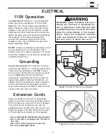
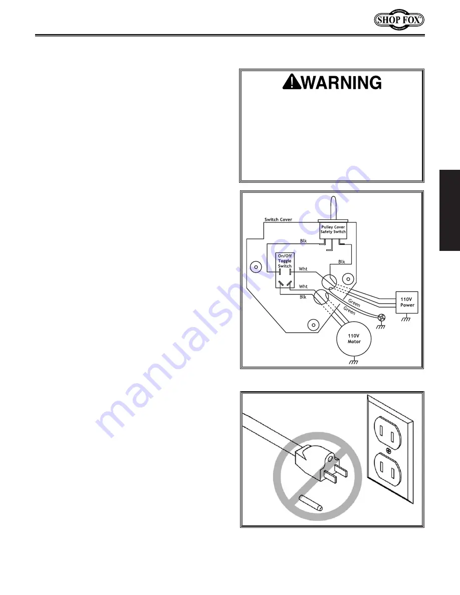
Figure 5a. 

Never remove grounding pin.

Figure 5. 

Model W1667 wiring diagram.

Ground this machine!

The electrical cord sup-

plied with the W1667 8 

1

2

'' Oscillating Drill Press

comes with a grounding pin. 

DO NOT

remove

the pin if your outlet does not accept a ground
pin, see 

Figure 5a

. Have the outlet box

replaced by a qualified electrician or have an
appropriate adapter installed. Remember, an
adapter with a grounding wire does not guaran-
tee the machine will be grounded. A ground
source must always be verified in the electrical
circuit within the wall or conduit.

Using an extension cord with an undersized
gauge or one that is too long, generates heat in
the cord that may cause fire or circuit damage.
If you must use an extension cord, use the
guidelines below to determine the correct cord
length and gauge. The amp rating of the motor
is 9 amps and can be found on its nameplate. 

•Use a cord rated for Standard Service (Grade S)
•Use a cord that is 16 gauge and 100 feet or

less only

•Use a cord with a ground wire and pin
•Use only undamaged cords

The 

SHOP FOX

®

W1667 8 

1

2

'' Oscillating Drill

Press can only be operated at 110 volts (see

Figure 5

). The  motor draws approximately 5

amps. Choose an outlet with a 10 amp circuit
breaker or fuse protection. Remember circuits
being used by other machines at the same time
add to the total electrical load being applied by
this machine. If this total amperage load
exceeds the amperage rating of the circuit
breaker or fuse, use a different circuit with a
higher amperage rating.

DO NOT 

modify an existing low-amperage circuit

by only replacing the circuit breaker with a
breaker rated for a higher amperage. The break-
er and the complete circuit must be replaced by
a qualified electrician.

DISCONNECT power to machine before per-
forming any electrical or mechanical ser-
vice or maintenance. Seek assistance from
a qualified electrician if you do not under-
stand the wiring diagram in this manual.
Always follow the applicable electrical
codes and standards. Otherwise serious
personal injury or death may occur!

ELECTRICAL

Extension Cords

Grounding

110V Operation

ELECTRICAL

Содержание SHOP FOX W1667

Страница 1: ... 1 360 734 3482 On Line Technical Support tech support shopfox biz COPYRIGHT 2000 BY WOODSTOCK INTERNATIONAL INC REVISED FEBRUARY 2004 WARNING NO PORTION OF THIS MANUAL MAY BE REPRODUCED IN ANY SHAPE OR FORM WITHOUT THE WRITTEN APPROVAL OF WOODSTOCK INTERNATIONAL INC ...

Страница 2: ...als are Lead from lead based paints Crystalline silica from bricks cement and other masonry products Arsenic and chromium from chemically treated lumber Your risk from these exposures varies depending on how often you do this type of work To reduce your exposure to these chemicals work in a well venti lated area and work with approved safety equip ment such as those dust masks that are specially d...

Страница 3: ...ing 7 Extension Cords 7 ASSEMBLY 8 Box Contents 8 Base and Column 9 Dust Port 9 Table 10 Headstock 11 Drill Chuck 12 Handles 12 ADJUSTMENTS 13 Belt Tension 13 Feed Shaft Spring Tension 14 Quill Shaft Screw 15 Table Height Tilt 16 Drilling Speed 17 Drill Press RPM Chart 18 Drilling Depth 18 Drill Cutter and Hole Saw Suggested RPM Chart 19 OPERATIONS 21 Starting the Drill Press 21 Drill Drum Changes...

Страница 4: ...nnection to your dust collection system The Model W1667 is packaged with a drill chuck motor and paddle switch with removable safety key Woodstock International Inc is committed to customer satisfaction in providing this manual It is our intent to make sure all the information necessary for safety ease of assembly practical use and dura bility of this product be included We stand behind our machin...

Страница 5: ... or fitness for any particular purpose are hereby limit ed to the duration of this written warranty We do not warrant that SHOP FOX machinery complies with the provisions of any law or acts In no event shall Woodstock International Inc s liability under this warranty exceed the purchase price paid for the product and any legal actions brought against Woodstock International Inc shall be tried in t...

Страница 6: ...s DO NOT operate this machine in wet or open flame environ ments Airborne dust particles could cause an explosion and severe fire hazard 6 Ensure all guards are securely in place and in working condition 7 Make sure switch is in the OFF position before connecting power to machine 8 Keep work area clean free of clutter grease etc 9 Keep children and visitors away All visitors should be kept at a sa...

Страница 7: ... designed 13 Use correct tool DO NOT force machine or attachment to do a job for which it was not designed 14 Wear proper apparel DO NOT wear loose clothing neck ties gloves jewelry etc 15 Remove adjusting keys and wrenches Before turning the machine on make it a habit to check that all adjusting keys and wrenches have been removed 16 Use proper extension cord When using an extension cord make sur...

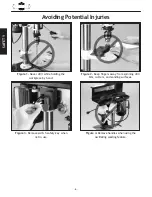
Страница 8: ...ece by hand Figure 2 Keep fingers away from spinning drill bits cutters and sanding surfaces Figure 3 Remove switch safety key when not in use Figure 4 Remove handles when using the oscillating sanding feature 6 Avoiding Potential Injuries SAFETY ...

Страница 9: ...e and 100 feet or less only Use a cord with a ground wire and pin Use only undamaged cords The SHOP FOX W1667 8 1 2 Oscillating Drill Press can only be operated at 110 volts see Figure 5 The motor draws approximately 5 amps Choose an outlet with a 10 amp circuit breaker or fuse protection Remember circuits being used by other machines at the same time add to the total electrical load being applied...

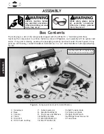
Страница 10: ... will be quicker and easier If any part is missing examine the packaging carefully and check under the belt guard If any parts are still missing contact Woodstock International Inc at 1 360 734 3482 or tech support shop fox biz 1 Headstock 2 Base 3 Column 4 Table 5 Dust Port 6 Drill Chuck and Key 7 Table Inserts 4 8 Spindle Handles 3 9 Cap Screw and Washers 10 Sanding Spindle 11 Hex Head Bolts 3 1...

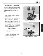
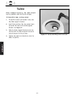
Страница 11: ... mounting holes and secure tightly with the three M8 1 25 x 16mm hex head bolts using the open end wrench provided Figure 7 Using holes as a drill guide To install the dust port do these steps 1 Position the two piece dust port to the bottom of the table See Figure 8 2 Insert the four M4 0 7 x 22mm Phillips head screws and tighten Figure 8 Installing the dust port The dust port directs suction to ...

Страница 12: ...ck shoe into the pocket locat ed inside the hole of the table support bracket See Figure 9 3 Slide the table support bracket onto the column until the table support bracket is near the bottom of the column 4 Tighten the table lock handle to lock the table in position When installed correctly the table should lock in position with firm lever torque 10 Table ASSEMBLY ...

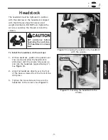
Страница 13: ...k approximately 2 See Figure 10 2 Align the headstock directly over the foot of the base as viewed from the front of the drill press 3 Tighten the two setscrews to secure the headstock to the column See Figure 11 GET assistance before beginning the next step The headstock is a heavy load The headstock must be tightened in position with the setscrew so the headstock is aligned with the drill press ...

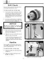
Страница 14: ...ral spirits and follow all safety warnings on the container Failure to clean the tapered mating surfaces of the spindle and drill chuck will result in the chuck falling off during use 2 Use the provided chuck key to adjust the jaws of the chuck until they are well inside the drill chuck body See Figure 12 3 Place the drill chuck on the spindle and insert the cap screw into the hole of the drill ch...

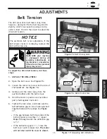
Страница 15: ... is correct when pinched together between the pulleys See Figure 17 If the gap between both inner sides of the belt is greater or less than 11 2 repeat Steps 3 through 6 until the deflection gap is 11 2 If the deflection gap is 11 2 close the belt cover until it snaps shut The motor will not start until the cover is closed NOTICE The oscillator belt is not adjustable If the belt shows cracks or is...

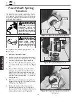
Страница 16: ...ke sure the quill shaft is completely seat ed and the depth stop reads 0 See Figure 19 4 Put on thick leather gloves and hold the spring cover against the side of the head stock so the cover stays splined with the locking lug remove the jam nut and loosen the cover nut approximately 1 4 6 4mm See Figure 19 5 Pull the cover outward just enough to dis engage the spring cover lock slot from the locki...

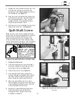
Страница 17: ...r as the screw can go without binding the quill hold the screw and tighten the jam nut 6 Recheck for quill binding and looseness while moving the quill up and down through its entire range of travel and re adjust as required Figure 22 Clean and oil quill shaft Figure 23 Typical quill shaft screw and jam nut UNPLUG your machine during all assembly adjustments and mainte nance procedures Otherwise s...

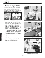
Страница 18: ...Loosen the table tilt lock bolt and use the tilt scale to find your desired drilling or sanding angle See Figure 26 5 Tighten the tilt table lock bolt SUPPORT table before loosening lock knob The weight of the table combined with the workpiece could result in a crushing injury You can adjust the table height and angle to accommodate for workpiece height or achieve special drilling sanding angles Y...

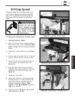
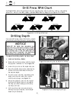
Страница 19: ...n the lock knob 8 Tighten the lock screw and make sure the belt deflection is 11 2 between both inner sides when the belt is pinched together between the pulleys Refer to Belt Tension in the ADJUSTMENTS section on Page 13 for details 9 Close the cover The motor will not start until the cover is closed Figure 27 Loosening the lock knob Figure 28 Adjusting belt to desired speed Figure 29 Motor suppo...

Страница 20: ... while maintaining this depth until the nut comes into contact with the stop flange See Figure 31 6 Allow the spindle to return to its original position and tighten the jam nut against the stop nut while making sure the stop nut does not move 7 Drill a test hole into scrap stock before drilling into any workpiece and readjust depth stop if necessary Figure 31 Nut contacting stop flange Figure 30 R...

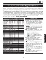
Страница 21: ... 19 ADJUSTMENTS ...

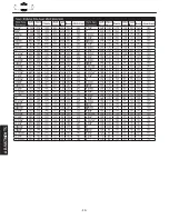
Страница 22: ... 20 ADJUSTMENTS ...

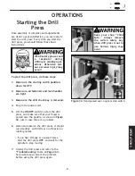
Страница 23: ...gure 32 just in case there is a problem 6 Listen and observe the drill press it should run smoothly with little or no vibration or rubbing noises If you hear strange or unusual noises shut the drill press OFF and wait for the spindle to stop moving 7 Unplug the drill press and refer to the Troubleshooting table on Page 26 to help isolate and correct the problem before using the drill press again F...

Страница 24: ...for drums and paper 4 Tighten the chuck with the chuck key using any of the three key end locations See Figure 34 5 Choose the insert that has an opening approximately 1 4 bigger than the sanding drum chosen For drilling always use the table insert with the smallest opening A table insert is not needed when a 2 drum is used See Figure 35 6 Install the chosen table insert into the pocket in the top...

Страница 25: ...il the cover is closed 6 Loosen the jam nut for the depth stop and adjust both nuts until they are positioned at the top of the depth stop rod Tighten the jam nut See Figure 38 Figure 36 Oscillator belt on storage bracket Figure 37 Stretch the belt to fit on pulleys Figure 38 Back off the depth stop nuts UNPLUG the machine and remove all handles before using the oscillating fea ture The handles sw...

Страница 26: ...sert 9 Loosen and pivot the table so the opening in the installed table insert is centered to the drill bit or sanding drum 10 Adjust the table height to use all of the grit on the paper as the paper wears If the thickness of the workpiece does not allow much table movement and the sanding drum paper is partially worn on one end remove the drum from the sand ing spindle turn it end for end and rep...

Страница 27: ...ble and other unpainted surfaces rust free with regular applications of products like Boeshield T 9 For long term storage con sider products like Kleen Bore s Rust Guardit NEVER adjust or service the machine while it is running Wait until the machine is turned off unplugged and all working parts have come to a stop before proceeding NOTICE Contrary to some beliefs worn abrasives are not the equiva...

Страница 28: ...this table to isolate and correct any problems with your drill press If you cannot correct a problem contact Woodstock International Inc at 1 360 734 3482 or tech support shopfox biz MAINTENANCE Troubleshooting ...

Страница 29: ... 27 Parts Diagram MAINTENANCE ...

Страница 30: ...99 LABEL MACHINE ID 100 X1667100 LABEL DEPTH CHART 102 XPW05M FLAT WASHER M4 103 XPS01M PHLP HD SCREW M4 0 7 X 8 REF PART DESCRIPTION 1 X1667001 BASE 2 X1667002 COLUMN 3 XPB09M HEX BOLT M8 1 25 X 20 4 X1667004 TABLE BRACKET 5 X1667005 TABLE 6 XPB25M HEX BOLT M12 1 75 X 25 7 X1667007 LOCK HANDLE M10 8 X1667008 HEAD CASTING 9 X1667009 SPECIAL DEFLECTION SCREW 10 XPN01M HEX NUT M6 1 0 11 X1667011 FEE...

Страница 31: ...re also available through online deal ers Please call or e mail Woodstock International Inc Customer Service to get a current listing of deal ers at 1 800 840 8420 or at sales woodstockint com D2677 Drum Sander Set includes three rubber sanding drums 41 4 in length to accommodate 1 11 2 and 2 diameter sanding sleeves This kit also includes one 80 grit sleeve for each drum to get things started D27...

Страница 32: ...enter point and Allen wrench D3161 Steelex Heavy Duty Carbide Tipped Adjustable Circle Cutter is Carbide Tipped and cuts 13 4 to 53 4 diameter holes in the toughest material For use with 1 2 drill press chucks Includes hex wrench and 7 16 pilot drill The SHOP FOX D2056 Tool Table is great for bench top tools like chop saws drill presses planers scroll saws and bandsaws Support cross braces on top ...

Страница 33: ...______________________ 1 Where did you purchase your SHOP FOX machine Store ____________________City ______________________ 2 How did you first learn about us ___Advertisement ___Friend ___Mail order Catalog ___Local Store ___World Wide Web Site ___Other__________________________________________________ 3 Which of the following magazines do you subscribe to ___American Woodworker ___Today s Homeow...

Страница 34: ...TAPE ALONG EDGES PLEASE DO NOT STAPLE FOLD ALONG DOTTED LINE FOLD ALONG DOTTED LINE WOODSTOCK INTERNATIONAL INC P O BOX 2309 BELLINGHAM WA 98227 2309 Place Stamp Here ...

Страница 35: ......

Страница 36: ......

Отзывы: