Owner Service
19
MAN1048 (4/16/2014)
3.
Align crossbar (1) with blade access hole in cutter
frame. Apply a liberal coating of Never Seez
®
or
equivalent to blade pin and crossbar hole. Make
sure blade offset is away from cutter. Push blade
pin through crossbar.
4.
Insert lock washer (4) and nut (5) through blade
access hole in deck. Install on blade pin (3) and
tighten to 450 lb-ft using a 1-11/16" socket.
NOTE:
Blade should be snug but should swivel on
pin without having to exert excessive force.
Blade Sharpening
NOTICE
■
When sharpening blades, grind the same
amount on each blade to maintain balance.
Replace blades in pairs. Unbalanced blades will
cause excessive vibration, which can damage
gearbox bearings. Vibration may also cause struc-
tural cracks to cutter.
1.
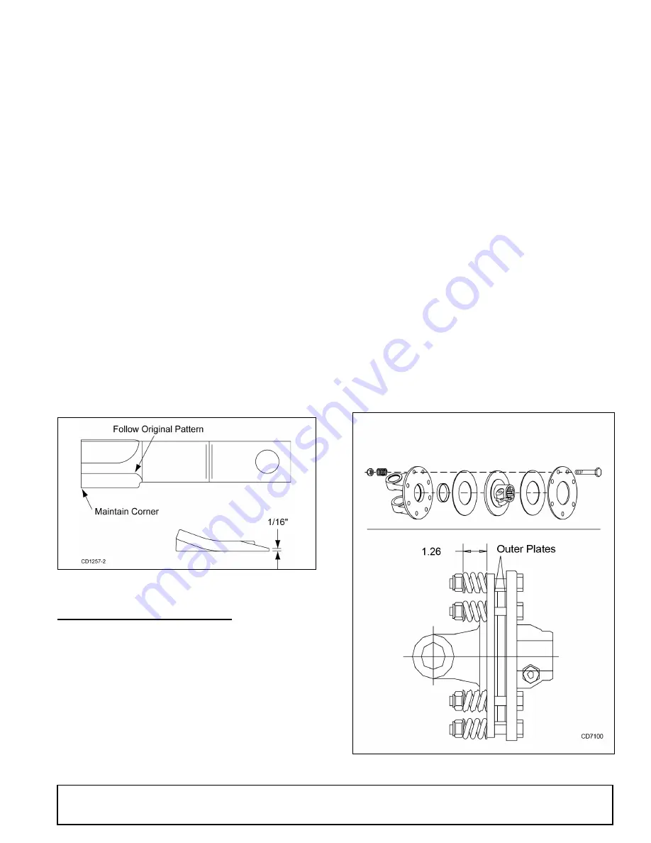
Sharpen both blades at the same time to maintain
balance. Follow original sharpening pattern.
2.
Do not sharpen blade to a razor edge—leave at
least a 1/16" blunt edge.
3.
Do not sharpen back side of blade.
Figure 11
. Blade Sharpening
SLIP CLUTCH ADJUSTMENT
The slip clutch is designed to slip so that the gearbox
and driveline are protected if the cutter strikes an
obstruction.
A new slip clutch or one that has been in storage over
the winter may seize. Before operating the cutter, make
sure it will slip by performing the following operation:
1.
Turn off tractor engine and remove key.
2.
Loosen nuts on springs until the springs can rotate
freely, yet remain secure on the bolts.
3.
Mark outer plates of slip-disc clutch as shown in
Figure 12.
4.
Securely attach implement to the tractor and start
the tractor.
5.
Engage PTO for several seconds then quickly
disengage it.
6.
Turn tractor off and remove key.
7.
The friction lining plates should have "slipped".
Check the marks placed on the outer plates of the
slip-disc clutch in step 3 to make sure this is the
case.
8.
If clutch does not slip, check assembly for oil,
grease and debris. Clean if necessary.
9.
Reassemble clutch and tighten bolts no more than
1/8 of a turn at a time until desired setting of 1.26"
is reached.
10.
If excessive slippage continues, check lining plates
for excessive wear. They are 1/8" thick when new
and should be replaced after 1/32" of wear to
ensure proper operation.
Figure 12
. Slip Clutch Assembly
Содержание RC3.5
Страница 1: ...OPERATOR S MANUAL ROTARY CUTTER Rev 3 17 2021 RC3 5 RC4 RC5 RC6 MAN1048...
Страница 29: ...Dealer Check Lists 29 MAN1048 4 16 2014 NOTES...
Страница 34: ...34 Assembly MAN1048 4 16 2014 NOTES...
Страница 36: ...36 Parts MAN1048 4 16 2014 MAIN ASSEMBLY...


