23
3062880_0910
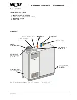
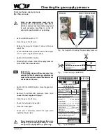
Checking the gas supply pressure
(Gas flow pressure)
• Set the ON/OFF switch to "0".
• Open the gas shut-off valve.
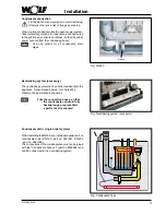
• Release the plug at test nipple
and vent the gas
supply line.
• Connect the differential pressure tester at test nipple
to "+", with "-" against atmosphere.
• Switch ON the ON/OFF switch.
• After starting the boiler, check the supply pressure
at the differential pressure tester.
Work on gas components must only be
performed by a licensed gas fitter. Work
which is carried out incorrectly may lead
to gas escaping, resulting in a risk of
explosion, asphyxiation or poisoning.
Checking the gas supply pressure
• Switch OFF the ON/OFF switch. Close the gas shut-
off valve.
• Remove the differential pressure tester and
re-seal the test nipple with plug
.
• Open the gas shut-off valve.
• Check the test nipple is gas-tight.
• Close the boiler again.
• Check and if necessary amend the type plate
regarding the gas type.
Natural gas:
If the supply pressure (flow pressure) lies
outside the 18 to 25 mbar range, adjustments
must not be carried out and the boiler must
not be taken into use.
NB
If any screws are not tightened, there is a
danger of gas escaping, leading to a risk
of explosion, asphyxiation or poisoning.
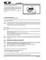
Fig.: Test nipple for checking the gas supply pressure
MGK-170/210/250/300
MGK-130
Gas-Brennwert-Heizgerät
1234567890
Herstellnummer
Nennwärmebelastung
Heizen
Nennleistung
Heizen 50/30°C
Heizen 80/60°C
Netzanschluß
Q = 28 - 160 k
W
P = 30 - 167 k
W
P = 27 - 156 k
W
90°C
230V ~ 50 Hz
280 W
Elektrische Leistungsaufnahme
Schutzart
Max. Vorlauftemperatur
Max. Betriebsdruck Heizkreis PMS = 6 bar
IP40
Wasserinhalt Heizwärmetauscher
087511121234567890
08
75
11
12
12
34
56
78
90
875
111
2
Art
.-N
r.
CE-0063BQ3805
A/D/CH
123
456
789
0
He
rst.
-Nr
.
08
Typ MGK-170
NO
x
Klasse
5
Kategorie
- G20 - 20 mbar
Bestimmungsland
Eingestellt auf
B23, B33, C33, C43, C53, C83
C63 gem. Montageanleitung
15 l
W
armwasser
Q = 28 - 160 k
W
Abgaswertegruppe nach DVGW 635
G
52
Art
8751156
06/08
DE/AT/CH
Der Kessel darf nur in einem Raum
installiert werden, der die maßgeblichen
Belüftungsanforderungen erfüllt.
Lesen Sie die Montage- bzw.
Betriebsanleitung bevor Sie den Kessel
installieren bzw. in Betrieb nehmen.
MG
K-1
70
E/H
II2ELL3P
DE
II2H3P
AT
2H
2E
CH
I2H
2H
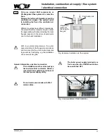
Fig.:
Type plate MGK
Fig.:
Conversion type plate MGK

