


10
W O L F
D UA L F U E L R A N G E S
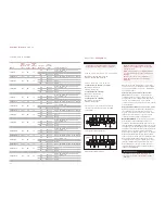
G A S
R A T I N G
Model #
Total Heat
Ouput
(Gas)
Gas
Units
Electrical
Rating
(Amps)
Appliance
Category
Types and
Pressures
(mbar)
Country of Designation
ICBDF304
17.1
kW
20
I2H
G20 at 20
AT, DK, EE, FI, GR, IE, IT, LT, NO, PT, ES,
SE, SI, SK, GB, CH
I2E
G20 at 20
DE, PL
I2E+
G20 at 20/25
BE, FR
ICBDF304-LP
1051
g/h
20
I3P
G31 at 37
BE, CZ, FR, GR, IE, NL, NO, PT, ES, GB, CH
ICBDF364C
22.7
kW
20
I2H
G20 at 20
AT, DK, EE, FI, GR, IE, IT, LT, NO, PT, ES,
SE, SI, SK, GB, CH
I2E
G20 at 20
DE, PL
I2E+
G20 at 20/25
BE, FR
ICBDF364C-LP
1425
g/h
20
I3P
G31 at 37
BE, CZ, FR, GR, IE, NL, NO, PT, ES, GB, CH
ICBDF364G
22.7
kW
20
I2H
G20 at 20
AT, DK, EE, FI, GR, IE, IT, LT, NO, PT, ES,
SE, SI, SK, GB, CH
I2E
G20 at 20
DE, PL
I2E+
G20 at 20/25
BE, FR
ICBDF364G-LP
1425
g/h
20
I3P
G31 at 37
BE, CZ, FR, GR, IE, NL, NO, PT, ES, GB, CH
ICBDF366
26.7
kW
20
I2H
G20 at 20
AT, DK, EE, FI, GR, IE, IT, LT, NO, PT, ES,
SE, SI, SK, GB, CH
I2E
G20 at 20
DE, PL
I2E+
G20 at 20/25
BE, FR
ICBDF366-LP
1632
g/h
20
I3P
G31 at 37
BE, CZ, FR, GR, IE, NL, NO, PT, ES, GB, CH
ICBDF484CG
28.3
kW
30
I2H
G20 at 20
AT, DK, EE, FI, GR, IE, IT, LT, NO, PT, ES,
SE, SI, SK, GB, CH
I2E
G20 at 20
DE, PL
I2E+
G20 at 20/25
BE, FR
ICBDF484CG-LP
1800
g/h
30
I3P
G31 at 37
BE, CZ, FR, GR, IE, NL, NO, PT, ES, GB, CH
ICBDF486C
32.3
kW
30
I2H
G20 at 20
AT, DK, EE, FI, GR, IE, IT, LT, NO, PT, ES,
SE, SI, SK, GB, CH
I2E
G20 at 20
DE, PL
I2E+
G20 at 20/25
BE, FR
ICBDF486C-LP
2007
g/h
30
I3P
G31 at 37
BE, CZ, FR, GR, IE, NL, NO, PT, ES, GB, CH
ICBDF486G
32.3
kW
30
I2H
G20 at 20
AT, DK, EE, FI, GR, IE, IT, LT, NO, PT, ES,
SE, SI, SK, GB, CH
I2E
G20 at 20
DE, PL
I2E+
G20 at 20/25
BE, FR
ICBDF486G-LP
2007
g/h
30
I3P
G31 at 37
BE, CZ, FR, GR, IE, NL, NO, PT, ES, GB, CH
ICBDF484DG
28.3
kW
30
I2H
G20 at 20
AT, DK, EE, FI, GR, IE, IT, LT, NO, PT, ES,
SE, SI, SK, GB, CH
I2E
G20 at 20
DE, PL
I2E+
G20 at 20/25
BE, FR
ICBDF484DG-LP
1800
g/h
30
I3P
G31 at 37
BE, CZ, FR, GR, IE, NL, NO, PT, ES, GB, CH
ICBDF484F
21.9
kW
30
I2H
G20 at 20
AT, DK, EE, FI, GR, IE, IT, LT, NO, PT, ES,
SE, SI, SK, GB, CH
I2E
G20 at 20
DE, PL
I2E+
G20 at 20/25
BE, FR
ICBDF484F-LP
1342
g/h
30
I3P
G31 at 37
BE, CZ, FR, GR, IE, NL, NO, PT, ES, GB, CH
ICBDF604CF
27.5
kW
40
I2H
G20 at 20
AT, DK, EE, FI, GR, IE, IT, LT, NO, PT, ES,
SE, SI, SK, GB, CH
I2E
G20 at 20
DE, PL
I2E+
G20 at 20/25
BE, FR
ICBDF604CF-LP
1716
g/h
40
I3P
G31 at 37
BE, CZ, FR, GR, IE, NL, NO, PT, ES, GB, CH
ICBDF606CG
37.9
kW
40
I2H
G20 at 20
AT, DK, EE, FI, GR, IE, IT, LT, NO, PT, ES,
SE, SI, SK, GB, CH
I2E
G20 at 20
DE, PL
I2E+
G20 at 20/25
BE, FR
ICBDF606CG-LP
2381
g/h
40
I3P
G31 at 37
BE, CZ, FR, GR, IE, NL, NO, PT, ES, GB, CH
R E Q U I R E D P O W E R S U P P LY
Single phase: 220-240V AC; 50/60 Hz
3phase: 380-415V AC; 50/60 Hz
M A X I M U M C O N N E C T E D L O A D
762 mm and 914 mm Dual Fuel ranges:
Single phase: 20 amps
3phase: 20 amps
1219 mm Dual Fuel ranges:
Single phase: 30 amps
3phase: 20 amps
1524 mm Dual Fuel ranges:
Single phase: 40 amps
3phase: 20 amps
Refer to the wiring diagram showing the
connections for each lead to the terminal box
on the unit.
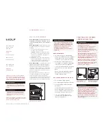
E L E C T R I C A L
R E Q U I R E M E N T S
The complete appliance must be properly
grounded at all times when electrical
power is applied.
NOTE: Improper connection can result in
a fire hazard.
Before obtaining access to terminals, all
supply circuits must be disconnected.
Verify that power is disconnected from
the electrical box before proceeding.
Open the terminal box to expose the screws
with corresponding numbers. Run the cord
through the strain relief hole and into the
terminal box.
For Single Phase Install (Line, Neutral,
Ground):
Loosen the 1, 5, and ground screws.
Attach the Neutral wire to the number 5
position. Line should be attached to the 1
postion and attach the ground to the corre-
sponding ground screw.
For 3phase Install (L1, L2, L3, Neutral,
Ground):
Loosen the 1, 2, 3 and remove the
copper bars. Loosen 5 and ground screws.
Attach L1 to position 1. L2 to position 2. L3 to
position 3. Neutral wire to position 5 and attach
the ground to the corresponding ground screw.
IMPORTANT NOTE:
Connection of this appli-
ance should be through a fused connection
unit or a suitable isolator, which complies with
national and local safety regulations. The
on/off switch should be easily accessible after
the appliance has been installed. If the switch
is not accessible after installation (depending
on country) an additional means of disconnec-
tion must be provided for all poles of the
power supply. When switched off there must
be an all pole contact gap of 3 mm in the
isolator switch. This 3 mm contact disconnect
gap must apply to any isolator switch, fuses
and/or relays according to EN60335.
Copper bars must be removed from posi-
tions 1, 2, and 3 when connecting to
3phase power.
Single phase wiring diagram
3phase wiring diagram
Содержание ICBDF304
Страница 62: ......
Страница 63: ......
Страница 64: ...64 WOLF APPLIANCE INC PO BOX 44848 MADISON WI 53744 USA WOLFAPPLIANCE COM 8 2 3 2 3 5 R E V A 5 2 0 1 3...