


2-12
Chapter 2: Installation
November 2007
Electronic
Connections
Complete the following electronic connections to the Top Box Connector Plate,
and
.
1
Gather all of the cables from the Top Box and confirm that there is access to the Top Box Connector
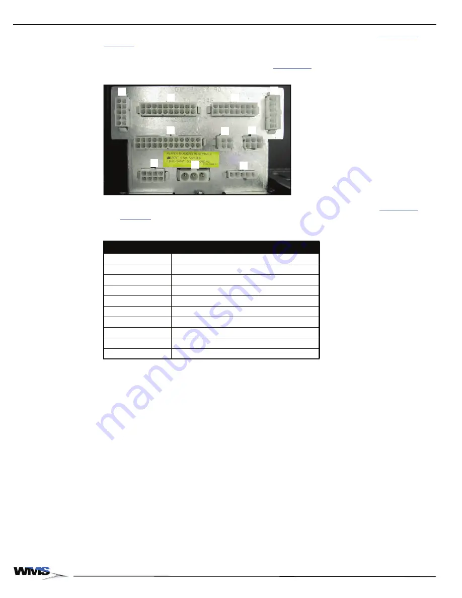
Plate, which is in the left section of the Top Box,
Figure 2-17 Top Box Connector Plate.
2
Make connections as needed based on the Top box being installed. Refer to
and
as needed.
Table 2-8 BBU Cabinet Top Box Connector Plate Designations.
Connector Plate Item
Function
A
Top Box/Aux Logic Player Tracking switched inputs
B
Top Box Serial Interface
C
Lamp Matrix
D
Player Tracking Power/Switch Interface
E
Player Tracking Door Switch
F
Top Box/Aux Logic switched inputs
G
Tower Light
H
Aux DC Power
I
Unswitched AC Power
J
Switched AC Power
A
B
C
D
E
F
G
H
I
J
Содержание Bluebird Series
Страница 2: ......
Страница 12: ...4 List of Figures November 2007 ...
Страница 16: ...4 About this Guide General Information October 2007 ...
Страница 101: ...5 13 Chapter 5 Exploded Views Block Diagram for BBU AC Power Distribution ...
Страница 102: ...5 14 Chapter 5 Exploded Views Block Diagram for BBU Bulkhead with CPU NXT ...
Страница 103: ...5 15 Chapter 5 Exploded Views Block Diagram for BBU Bulkhead with CPU NXT ...
Страница 104: ......


