Subject to changes without notice !
Änderungen vorbehalten !
Gearless Lift Machine
WSG-25
Operating Instructions
EN
Code: GM.8.002673.EN
Date:
07. May 2019
Version: 0.13a
Page: 25
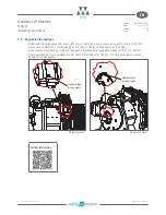
8.5. Individual check of the brake function
Only perform this test if necessary, e.g. after an emergency evacuation by mechanical manual means.
DANGER
f
All work on the brakes may only be carried out when the lift system is at a standstill. Unit power-off. Lock out and
tag out.
f
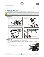
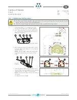
Carry out the test one after the other on the individual partial brakes of the lift machine.
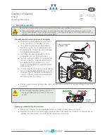
I. Release the brake
1.
1
2
5
2.
1
3
650 mm
Brake
Bowden cable
Lever extension
Spring force measuring device
Manual release lever
3.
N
0
100
200
300
400
500
1
3
4
L
H
=
750
mm
4.
N
0
100
200
300
400
500
1
3
4
~ 90° !
!
up to 200
N
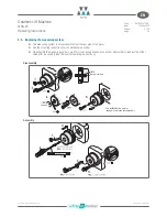
II. Applied the brake
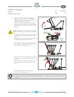
1. Remove the spring force measuring device (4) and the lever extension (3).
2. The manual release lever (5) must return to the initial position. Observe the marking in point I./1. (Initial position of the
brake).
3. Brake torque has been built up. The brake must not be
released. No air gap between brake disc and brake lining.
Traction sheave
Brake
Brake lining
No air gap !
Brake disc
No air gap !
Brake lining
4. If not, it is strongly recommended to shut down the lift
system.
Mark the initial position of manual release lever (5) on
the brake (e.g. with a text marker). Unhinge the Bowden
cable of manual brake release.
Fix a spring force measuring device (4) at the connecting
position L
H
= 750 mm.
Pull on the spring force measuring device (4) with up to 200 N.
Attach lever extension
(3) - tube with length of
650 mm.
Attention:
The angle a between
the lever/tube (3) and the spring
force measuring device (4) must
be approx. 90° during the complete
measuring procedure!
Содержание WSG-25
Страница 82: ...Notes INTORQ BA 14 0201 04 2016 36 Notes...

