background image

13


Ins
tall
at

Ion

Precautions before installation

Be well-informed of precautions before installation as follows.


y

The camera should be installed to a wall or ceiling that wears as much as 5-times weight of the camera.


y

When a cable is trapped in improper location or its skin is damaged, it may cause the product damage or fire.


y

Before installation, focus, zoom, etc. of the camera should be adjusted.


y

During installation, access by unnecessary persons should be prevented.

Installation

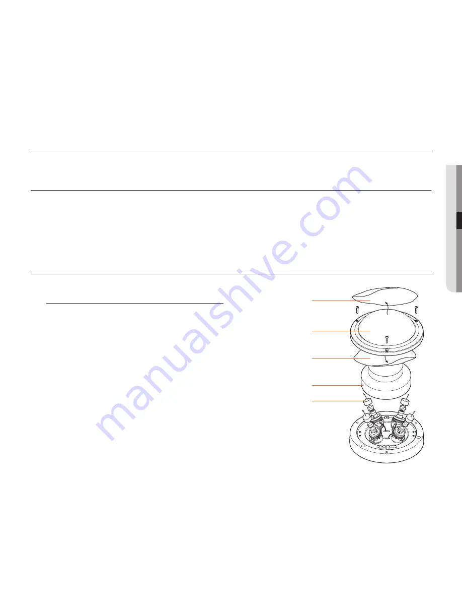
Dome cover protection 

sticker (outer side)

Dome cover

Lens cap

how to disassemble

1. 

Use L wrench to loosen camera dome cover screws.

2. 

Remove the camera module protection PEfoam.

3. 

Remove the camera cap.

4. 

Remove the dome cover inner protection sticker.

5. 

Remove the dome cover outer protection sticker.

how to install the camera

Dome cover protection 

sticker (inner side)

camera module protection 

PEfoam

Содержание HCM-9020VQ

Страница 1: ...HCM 9020VQ 4 Channel Multi Directional Camera User Manual ...

Страница 2: ...no circumstances this document shall be reproduced distributed or changed partially or wholly without formal authorization Disclaimer Hanwha Techwin makes the best to verify the integrity and correctness of the contents in this document but no formal guarantee shall be provided Use of this document and the subsequent results shall be entirely on the user s own responsibility Hanwha Techwin reserve...

Страница 3: ...ard do not expose this appliance to rain or moisture To prevent injury this apparatus must be securely attached to the floor wall in accordance with the installation instructions WARNING 1 Be sure to use only the standard adapter that is specified in the specification sheet Using any other adapter could cause fire electrical shock or damage to the product 2 Incorrectly connecting the power supply ...

Страница 4: ...UTION 1 Do not drop objects on the product or apply strong shock to it Keep away from a location subject to excessive vibrationor magnetic interference 2 Do not install in a location subject to high temperature over 55 C low temperature below 30 C or high humidity Doing so may cause fire or electric shock 3 If you want to relocate the already installed product be sure to turn off the power and the...

Страница 5: ...e disposed of with other household waste at the end of their working life Where marked the chemical symbols Hg Cd or Pb indicate that the battery contains mercury cadmium or lead above the reference levels in EC Directive 2006 66 If batteries are not properly disposed of these substances can cause harm to human health or the environment To protect natural resources and to promote material reuse pl...

Страница 6: ...required when the apparatus has been damaged in any way such as powersupply cord or plug is damaged liquid has been spilled or objects have fallen into the apparatus the apparatus has been exposed to rain or moisture does not operate normally or has been dropped 15 This product is intended to be supplied by a Listed Power Supply Unit marked Class 2 or LPS and rated from 24 Vac 50 60 Hz min 0 6 A o...

Страница 7: ...erated under wet environ ments 4 The camera surface should not be cleaned by harsh abrasive When it gets dirty it should be cleaned with dry towel 5 The camera is installed in cool places where there is no direct sunlight The direct sunlight may cause bad affect on the product Hanwha Techwin cares for the environment at all product manufacturing stages and is taking measures to provide customers w...

Страница 8: ...amera monitoring direction Connection 18 18 How to connect cables 19 How to connect alarm output terminal 20 How to connect monitors Camera operation 21 21 How to configure OSD menu of each camera 23 Menu configuration 24 How to configure functions 25 Exposure compensation 29 Color 30 Day and night mode 31 Image ADJ 32 Motion 33 Privacy 35 Setup 36 Exit Contents Troubleshooting 37 37 Troubleshooti...

Страница 9: ...eo BNC Output y y SENS UP Super Low Light Technology y y True Day Night Mechanical IR Cut Filter y y Dynamic Range Compressor DRC Reveals Low Light Detail Introduction y y Wide Dynamic Range WDR y y Smart DNR 3D Digital Noise Reduction y y High Light Compensation HLC y y Programmable Privacy Zones y y Auto Gain Control AGC y y Backlight Compensation BLC y y Auto White Balance AWB y y RS 485 Built ...

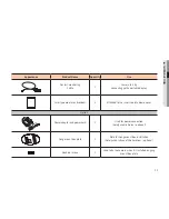
Страница 10: ...ame Quantity Use Camera 1 4 Channel Multi Directional Camera Simple Instructions 1 Tapping screws 3 Used to install on ceilings walls etc Plastic anchors 3 To tighten screws to installation places Inserted to holes To reinforce the installation Template 1 Installation Guide L wrench 1 Used for assembly and disassembly of dome covers ...

Страница 11: ...sture absorbent 2 Attached to the inner side of a dome cover Option Power adapter and power cord 1 Used for power connection Solely used in Korea optional Gang mount box plate 1 Plate for Gang mount box installation Solely used in Area of the Americas optional Machine screws 3 Used to fix the camera when it is installed on gang mount box plate ...

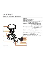
Страница 12: ... down right left direction or to change a value or state 4 channel change over switch When entering the initial OSD Menu it is possible to configure after arbitrary switch operation 2nd Analog video output terminal terminal for video output verification during installation 8 RS485 Control terminal It is connected to AHD DVR or a keyboard and cable of controlling OSD menus Alarm output terminal ter...

Страница 13: ...installation focus zoom etc of the camera should be adjusted y y During installation access by unnecessary persons should be prevented Installation Dome cover protection sticker outer side Dome cover Lens cap How to disassemble 1 Use L wrench to loosen camera dome cover screws 2 Remove the camera module protection PEfoam 3 Remove the camera cap 4 Remove the dome cover inner protection sticker 5 Re...

Страница 14: ... not to damage the cable It should be trimmed up 5 Refer to How to adjust monitoring direction of the camera and adjust the lens in a direction you want 6 Assemble the dome cover into the body 7 Remove the dome cover protection sticker M M If a wall or ceiling is not strong enough to sustain the camera it may fall So after the installation surface is reinforced it should be installed Use L wrench ...

Страница 15: ...Be careful not to damage the cable It should be trimmed up 3 Refer to How to adjust monitoring direction of the camera and adjust the lens in a direction you want 4 Assemble the dome cover into the body 5 Remove the dome cover protection sticker M M Use L wrench to tightly fix dome cover screws Gang mount box plate solely used in area of the Americas optional ...

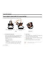
Страница 16: ...1 fixed to 0º when it is attached to the center of a magnetic plate 2 20 60º when it is attached to a side of a magnetic plate How to adjust 1 After attaching the camera on Magnetic board the panning angle is adjusted considering the monitoring direction 2 The horizontal angle is adjusted such that the video reversal does not occur during rotation 3 Adjust the tilting angle to face on the monitori...

Страница 17: ...ndom 20 0 60 INSTALL GUIDE ANGLE SIDE CENTER 1 180 configuration 2 Random configuration 3 Random configuration 4 Random configuration M M When mounting the camera module on the side the quality of the image will not be guaranteed if the tilt angle of the camera exceeds the recommended angle When a camera module is installed at the right angle of 0º it should be located on the center ...

Страница 18: ...MAX_TDN ON 2 5 1 4 ch AHD BNC outputs AHD_Ch 1 to AHD_Ch 4 of each camera are connected to a DVR that supports AHD video 6 How to connect alarm terminal Alarm terminal connection method Camera alarm cables are connected to and terminals of sensor alarm devices and it operates in short or open circuit method according to alarm occurrence or not 1 DOUT ORANGE 3 DOUT GREEN 1 DOUT RED 3 DOUT GRAY 2 DO...

Страница 19: ... in Open Collector method it may be broke down When it is connected to devices that use excessive voltage or current please refer to Alarm output connection diagram 1 Alarm operation Alarm terminal connection method Camera alarm cables are connected to and terminals of sensor alarm devices and it operates in short or open circuit method according to alarm occurrence or not 1 Short circuit for alar...

Страница 20: ...r for 60 seconds through an analog monitor In order to continuously monitor the same channel after 60 seconds please change 4 ch change over switch to a different channel and then select a channel you want Be sure to connect devices while the power is off R L UP D REC HDD ALARM NETWORK BACKUP POWER AHD DVR BNC Cable BNC Cable Monitor Installation monitor 300 0 2nd analog video output DC 12V AC 24V...

Страница 21: ...of 4 channels by using external peripheral devices through RS485 communication 3 There are OSD function configuration button and 4 ch change over switch in OSD control board of the camera 2nd analog video output of a selected channel can be displayed on CRT monitor by using 4 ch change over switch and it is possible to configure OSD as well 2nd analog video output can be checked by CRT monitor 2nd...

Страница 22: ...utton 2nd analog video output can be checked by CRT monitor 2nd analog video output availability is notified on the upper right corner of AHD video for 60 seconds BNC Local Output for Sensor 1 BNC Local Output for Sensor 2 BNC Local Output for Sensor 4 BNC Local Output for Sensor 3 M M During the initial OSD menu entry 4 ch change over switch is arbitrarily modified just once for the first time an...

Страница 23: ...GC MARGIN 0 20 DELAY LOW MIDDLE HIGH RETURN Move to the startup menu FUNCTION SHARPNESS 0 10 GAMMA 0 45 0 75 MIRROR OFF ON FLIP OFF ON D ZOOM x1 0 x16 0 RETURN Move to the startup menu Function Configuration Menu MOTION MOTION OFF ON DET WINDOW SENSITIVITY 0 10 TEXT ALARM OFF ON ALARM OUT OFF ON RETURN Move to the startup menu PRIVACY BOX OFF ON POLYGON OFF ON RETURN Move to the startup menu SETUP...

Страница 24: ...he OSD function setting button y y Adjust the OSD function setting button to indicate an item you want 3 Use the OSD function setting button to change the current state 4 If you want to end select EXIT button and then push the OSD function setting button to end M M You can move from a mode that has to its lower menu by pushing the function setting button Modes with cannot be used according to the ...

Страница 25: ...ness changes the level according to the ambient brightness y y Shutter Sets the shutter speed to Auto Manual or Flicker less mode M M Auto Indoor is set under indoor environments Outdoor is set under outdoor environments If Manual is set the shutter spped can be adjusted as 1 30 1 60 1 120 1 30000 EXPOSURE LENS BACKLIGHT OFF DRC OFF DEFOG OFF AGC 10 SENS UP x4 3D DNR HIGH RETURN LENS BRIGHTNESS 8 ...

Страница 26: ...he subject the backlighted area is set separately to help identify the subject H POS moves a Zone location right left V POS moves a Zone location up down H Size changes a horizontal Zone size V Size changes a vertical Zone size y y Wide Dynamic Range When there is bright area around the subject indoors the function helps simultaneously identify both bright and bright areas around the subject When ...

Страница 27: ...r to help to better identify foggy objects or ambient scenes due to fog When DEFOG is set to Manual its level can be set to Low Middle and High But when DEFOG mode is used DRC menu setting is changed to mode y y Auto DEFOG is automatically set according to any any operation environment y y Manual Forces the DEFOG function to operate y y Level changes DEFOG weighting factors EXPOSURE LENS BACKLIGHT...

Страница 28: ...tness SENS UP Under low light levels users can set the mode for a better view of objects or ambient scenes and its default value is X2 Its setting level can be set to Off X2 X4 X8 X16 and X32 A higher level produces brighter video under low light levels But in a higher level there may occur video echo phenomenon 3D DNR 3D Digital Noise Reduction Under dark environments AGC function operates and pr...

Страница 29: ... arbitrarily set the feeling of screen color to compensate the feeling of color naturally C TEMP basic level is 5 000K the level can have one of 5000K 8000K and 3000K R Gain level of a warm feeling is 0 20 and users control the feeling of red color B Gain level of a cold feeling is 0 20 and users control the feeling of blue color Color Gain y y Color gain Users can naturally set a concentration le...

Страница 30: ... If the range value is set so low a margin between day time and night time is so low and the day and night mode may be repeated frequently The default setting value is 18 Dwell Time sets a delay time of the day and night mode y y Color maintains the color state regardless of ambient environments When the color mode is set Duration Range and Dwell Time cannot be changed to mode y y B W maintains th...

Страница 31: ...an be set among 7 levels by users H REV V REV y y H REV_USE It is possible to reverse video or image display on a monitor in the direction of left and right and it can be set by users y y V REV_USE It is possible to reverse video or image display on a monitor in the direction of up and down and it can be set by users D Zoom Users can set the level in order to enlarge a subject in the central area ...

Страница 32: ...nes y y Mode uses or not each Zone y y DET H POS moves Zone left right y y DET V POS moves Zone up down y y DET H Size changes horizontal Zone size y y DET V Size changes vertical Zone size Sensitivity sets the operation sensitivity OSD displays the status of alarm occurrences y y Motion When there is any motion in the camera video image Motion alarm is generated MOTION MOTION ON DETWINDOW SENSITI...

Страница 33: ...y y Zone DISP turns off or on a corresponding area and sets Privacy Zone y y H POS moves Zone left right y y V POS moves Zone up down y y H Size changes horizontal Zone size y y V Size changes horizontal Zone size y y Y LEVEL sets Zone brightness y y CR LEVEL CB LEVEL sets Zone color y y Transparency sets Zone transparency PRIVACY BOX ON POLYGON OFF RETURN BOX ZONE NUM 0 ZONE DISP ON H POS 0 V POS...

Страница 34: ...lygon of a corresponding area vertically y y POS1 X adjusts the upper right part left right y y POS1 Y adjusts the upper right part up down y y POS2 X adjusts the lower right part left right y y POS2 Y adjusts the lower right part up down y y POS3 X adjusts the lower left part left right y y POS3 Y adjusts the lower right part left right y y Y LEVEL sets Zone brightness y y CR LEVEL CB LEVEL sets ...

Страница 35: ...camera name on the upper right upper left lower right or lower left corner of the screen FRAME RATE Users can configure the default resolution of a video to 1080_30P or 720_30P Language Users can select an OSD language among 16 INIT At the current specified channel it is initialized to the initially configured OSD menu values When each channel is needed to be initialized it can be executed by the ...

Страница 36: ...mera operation EXIT SAVE EXIT Changed values are saved and the device exits from the OSD Menu EXIT Changed values are not saved and the device exits from the OSD Menu Return Moves to the upper menu EXIT SAVE EXIT EXIT RETURN ...

Страница 37: ... the screen is not clear Is there dust on the lens Clean the lens with clean cloth or brush Adjust the monitor state When bright light comes in the screen adjust the camera location or angle Check manual focus and zoom adjust of the lens You d better use a field test monitor When the screen is dark Adjust the state of a monitor or DVR Check if the termination process between systems is well done W...

Страница 38: ... 8 0 Megapixel 4x 1920x1080 Sensors Minimum Scene Illumination Video Output Color at Day 0 1Lux 4mm F2 6 30IRE 0 1Lux or below 6mm F2 0 30IRE B W at Night 0 01Lux 4mm F2 6 50IRE 0 01Lux or below 6mm F2 0 50IRE 4x AHD 1080p at 30fps Alarm Output 4x Alarm Outputs LENS Focal Length Lens Type 4 0mm X 2 6 0mm X 2 Fixed Lenses ENVIRONMENTAL Operating Temperature Humidity 30 C 50 C 90 RH or lower When th...

Страница 39: ...er Requirements DC12V AC24V Dual Voltage Power Consumption DC12V 0 7A 6 7W MAX_TDN ON AC24V 0 6A 7 3W MAX_TDN ON MECHANICAL Housing Material and Dimensions Aluminum 199 x 89 5 7 83 x 3 52 In Weight 4 4 lbs 2kg This specification may be modified for improvement without prior notification ...

Страница 40: ...Specifications 40_ Specifications Dimension Unit mm inch ...

Страница 41: ...MEMO ...

Страница 42: ...www hanwha security com Hanwha Techwin America 500 Frank W Burr Blvd Suite 43 Teaneck NJ 07666 Toll Free 1 877 213 1222 Direct 1 201 325 6920 Fax 1 201 373 0124 www hanwha security com Hanwha Techwin Europe Heriot House Heriot Road Chertsey Surrey KT16 9DT United Kingdom Tel 44 1932 57 8100 Fax 44 1932 57 8101 www hanwha security eu ...

Отзывы: