background image


54 

IP65 Stainless B Series Panel PC User Manual 

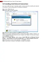
5.3 Installing Intel Sideband Fabric Device Driver  

Only for Windows 8 

Step  1

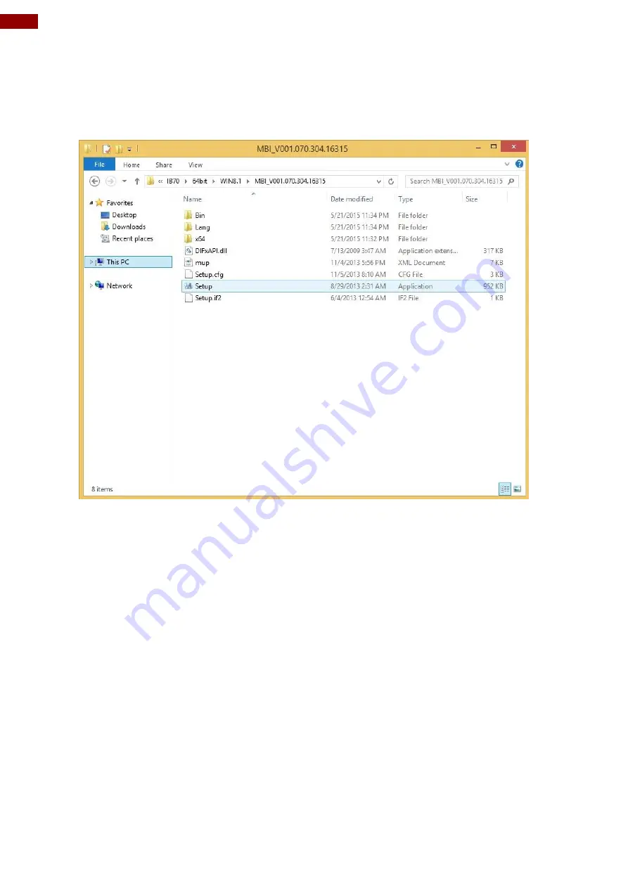
  Insert  the  CD  that  comes  with  the  motherboard.  Open  the  file  document 

“MBI”

  and 

click 

“Setup.exe”

 to install the driver. 


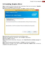
Step 2

 Welcome to the setup program window will appear, click 

Next

 to start the installation. 

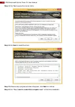
Step 3

 Carefully read the License Agreement terms and click 

Yes

 to agree. 

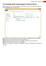
Step  4 

Setup progress will appear, please wait for the operations to be performed, then click 

Next 

to continue. 

Step 5 

The installation is complete, c

lick “

Yes, I want to restart this computer now” 

to finish 

and restart the computer.  


Содержание B Series

Страница 1: ... them for future reference IP65 Stainless B Series Panel PC with Push Buttons Intel Celeron N2930 2M Cache up to 2 16 GHz 10 1 15 19 21 5 Model No W10IB3S SPH1 B R15IB3S SPC3 B R19IB3S SPM1 B W22IB3S SPA3 B User Manual Document Version 1 0 Document Part No 91521110105V ...

Страница 2: ...Connecting Peripherals 17 2 2 1 Power Connector 18 2 2 2 LAN Connector 18 2 2 3 USB Connector 19 2 2 4 USB Type A Connector 19 2 2 5 RS 232 Connector 20 2 2 6 Connector 1 for Push Button Extension 20 2 2 7 Connector 2 for Push Button Extension 21 2 3 Cleaning the Monitor 21 Chapter 3 Operating the Device 22 3 1 Connecting to Power Source 22 3 2 Turning On Off the Device 23 3 3 Emergency Stop 23 3 ...

Страница 3: ... Installing Intel Sideband Fabric Device Driver 54 5 4 Installing Intel Trusted Engine Interface Driver 55 5 5 Installing Intel Network Connections 56 5 6 Installing Audio Driver 57 Chapter 6 Maintenance and Troubleshooting 58 6 1 Cleaning the Monitor 58 6 2 Basic Troubleshooting 58 Appendix 59 Appendix A Hardware Specifications 59 Appendix B Winmate Software Development Kit 61 ...

Страница 4: ...y energy and if not installed and used in accordance with the instruction manual may cause harmful interference to radio communications Operation of this equipment in a residential area is likely to cause harmful interference in which case the user will be required to correct the interference at him own expense European Union Electromagnetic Compatibility Directive 2014 30 EU EN55024 2010 A1 2015 ...

Страница 5: ...nvoice date If the customer discovers a defect we will at his her option repair or replace the defective product at no charge to the customer provide it is returned during the warranty period of one year with transportation charges prepaid The returned product must be properly packaged in its original packaging to obtain warranty service If the serial number and the product shipping data differ by...

Страница 6: ...electronics personnel should open the PC chassis Avertissement Toujours débrancher le cordon d alimentation du chassis lorsque vous travaillez sur celui ci Ne pas brancher de connections lorsque l alimentation est présente Des composantes électroniques sensibles peuvent être endommagées par des sauts d alimentation Seulement du personnel expérimenté devrait ouvrir ces chassis Caution Always ground...

Страница 7: ...3 B R19IB3S SPM1 B and W22IB3S SPA3 B The documentation set for the IP65 Stainless B Series Panel PC with Push Buttons provides information for specific user needs and includes User Manual contains detailed description on how to use the Panel PC its components and features Quick Start Guide contains detailed description on how to use the Panel PC its components and features Note Some pictures in t...

Страница 8: ...e and quick way to shut down the process In terms of machine integration push button devices are easy to install and wire and straightforward for understanding the function and use Averagely the wiring time is saved by over 60 and the installation cost is reduced by more than 30 1 2 Features The IP65 Stainless B Series Panel PC features 10 1 15 19 21 5 LCD with projected capacitive multitouch scre...

Страница 9: ...PO12050006 For 10 1 84W Part No 90PO12084000 15 up Varies by country External USB Cable with Waterproof Connector External VGA Cable with Waterproof Connector External USB LAN Cable with Waterproof Connector External COM Cable with Waterproof Connector External Cables for CN1 CN2 with Waterproof Connector Part No 9480128080K0 Part No 94I0080080KF Part No 94E0128040K0 for 10 1 Part No 94G0123090Q0 ...

Страница 10: ...on contains mechanical drawing of the IP65 Stainless B Series Panel PC with Push Buttons Notice that this is a simplified drawing and some components are not marked in detail 10 1 W10IB3S SPH1 B Unit mm Dimensions 293 x 250 x 69 mm Description Description USB LAN CN1 COM CN2 Power ...

Страница 11: ...11 Chapter 1 Introduction 15 R15IB3S SPC3 B Unit mm Dimensions 426 x 301 x 69 mm Description Description USB x 2 CN2 COM LAN CN1 Power 19 R19IB3S SPM1 B Unit mm Dimensions 516 x 395 x 69 mm ...

Страница 12: ...ption USB x 2 CN2 COM LAN CN1 Power 21 5 W22IB3S SPA3 B Unit mm Dimensions 595 x 337 x 69 mm Description Description USB x 2 CN2 COM LAN CN1 Power 1 5 Front Side USB Type A Connector The B Series Panel PC 15 up has one waterproof USB Type A connector on the front side ...

Страница 13: ...ps all operations immediately motors valve etc Emergency stop conditions shall be hard wired withdraw power from everything 2 Programmable Function Keys Three programmable function keys functions to be defined by customer 1 7 Rotary Switch for Touch Mode The IP65 Stainless B Series Panel PC features rotary switch for quick changing a touch mode located on the front side of the Panel PC Use rotary ...

Страница 14: ...touchscreen accepts touch inputs from bare fingertips Supports input by Rubber tip passive stylus Bare fingertips Glove In Glove mode the touchscreen supports inputs while the user is operating the touchscreen with gloves on Supports input by Glove Rubber tip passive stylus Bare fingertips 1 8 Rear Side Physical Buttons Physical buttons are located on the OSD panel at the rear side of the Panel PC...

Страница 15: ...pter 1 Introduction 1 9 LED Indicators LED indicators are located on the OSD panel at the rear side of the Panel PC LED Indicator Status Description On Power is on Off Power is off Blinking Stan by Off Normal ...

Страница 16: ...in use cover connector with waterproof cap Attention Lorsqu il n est pas utilisé couvrez le connecteur avec un capuchon étanche 2 1 Mounting The IP65 Stainless B Series Panel PC devices come with different mounting options suitable for most of the industrial and commercial applications 2 1 1 VESA Mount The Panel PC has VESA mount holes on the rear side Follow instructions below to mount the unit w...

Страница 17: ...B Series Panel PC has waterproof connectors with protection caps M12 power connector M12 GigaLAN connector M12 RS232 connector M12 USB connector two M12 connectors for push button extension and one waterproof connector USB2 0 type A 15 up The pin assignment of the connectors is described in this section Important To maintain the IP65 rating of the full unit it is recommended to use only IP65 water...

Страница 18: ...ult the B Series Panel PC has one M12 waterproof power connector that accepts 12V DC power input based on your order Power Cable 2 2 2 LAN Connector The B Series Panel PC has one M12 connector for GigaLAN Use waterproof LAN cable to connect the Panel PC to the Internet LAN Cable ...

Страница 19: ...USB cable to connect Panel PC to external peripherals such as mouse or keyboard USB Cable 2 2 4 USB Type A Connector The B Series Panel PC 15 19 21 5 has one waterproof USB Type A connector located on the front side Pin assignment and signal name of USB 2 0 connector for optional touch Pin Signal Name Pin Signal Name 1 5V 2 Data 3 Data 4 GND ...

Страница 20: ...Connector The B Series Panel PC has one M12 connector for RS 232 Use waterproof USB cable to connect Panel PC to external peripherals such as printer or keyboard RS 232 Cable 2 2 6 Connector 1 for Push Button Extension Push Button Extension Cable for Connector 1 ...

Страница 21: ...eaning Use water up to 80 C to clean the housing Wipe the screen with a clean soft lint free cloth This removes dust and other particles The display area is highly prone to scratching Do not use ketene type material ex Acetone Ethyl alcohol toluene ethyl acid or Methyl chloride to clear the panel It may permanently damage the panel and void the warranty If it is still not clean enough apply a smal...

Страница 22: ...ce Follow the following steps to connect your device to AC power source 1 Install conduit pipe and I O cover following the procedure described in the previous sections 2 Connect open wires to AC adapter 3 Connect the power cord to AC adapter 4 Plug the power cord to the AC outlet AC Adapter specifications and Panel PC power consumption vary by LCD panel size Size 10 1 15 19 21 5 AC Adapter 12V 50W...

Страница 23: ...o be ready to start again immediately on pressing start button 3 3 Emergency Stop For emergency stop press Emergency Shutdown Button located on the front side of the Panel PC Pressing this button stops all operations immediately motors valve etc Emergency stop conditions shall be hard wired withdraw power from everything 15 up 10 1 3 4 Operating System IP65 Stainless B Series Panel PC supports Win...

Страница 24: ...left to right with one finger Mouse drag Selection Drag one finger left right Zoom Zoom default to CTRL key scroll wheel Move two fingers apart toward each other Rotate No system default unless handled by Application using WM_Gesture API Move two fingers in opposite directions or Use one finger to pivot around another Press and Hold Right click Press wait for blue ring animation to complete then r...

Страница 25: ...lly feed time or disable watchdog Example Every 10 min watchdog will monitor the system in case any error occurs the system will restart automatically when the countdown time reaches 0 Every 9 min watchdog timer will be reset to 10 min Setting Description Watchdog Countdown Time The system automaticity restarts when this countdown time reaches zero Default 10 min Periodically Feed Time To set a cy...

Страница 26: ...ttings 3 Modifying the specific hardware specifications 4 Necessity to optimize specifications BIOS Navigation Keys The following keys are enabled during POST Key Function Del Enters the BIOS setup menu F7 Display the boot menu Lists all bootable devices that are connected to the system With cursor and cursor and by pressing ENTER select the device used for the boot Pause Pressing the Pause key st...

Страница 27: ...tting Description Setting Option Effect System Language Displays the system language English is set up by default Adjustment of the language Set the language in other language The language in this device is English System Date Time This is current date setting The time is maintained by the battery when the device is turned off Date and time changes Set the date in the format mm dd yyyy The time in...

Страница 28: ...rtant Handle advanced BIOS settings page with caution Any changes can affect the operation of your computer Advanced Configuration and Power Interface ACPI settings allow to control how the power switch operates The power supply can be adjusted for power requirements You can use the screen to select options of ACPI configuration A description of the selected items will appear on the right side of ...

Страница 29: ... Enter Opens submenu PPM Configuration Configures PPM settings Enter Opens submenu Thermal Configuration Configures Thermal Parameters Enter Opens submenu IDE Configuration Configures IDE Parameters Enter Opens submenu Miscellaneous Configuration Configures Miscellaneous Parameters Enter Opens submenu CSM Configuration Configures CSM Parameters Enter Opens submenu USB Configuration Configures USB ...

Страница 30: ...for power requirements You can use the screen to select options of ACPI configuration A description of the selected items will appear on the right side of the screen BIOS Setting Description Setting Option Effect Enable ACPI Auto Configuration BIOS ACPI Auto Configuration Enable Disable Enables or Disables this function Enable Hibernation Control hibernation Enable Disable Enables or Disables this...

Страница 31: ...nge the value of the option selected A description of the selected item appears on the right side of the screen Serial Port 1 5 Use these items to set parameters related to serial port 1 5 Watch Dog Time Select You can either disable Watch Dog Time Select or set up the time Use Arrow keys to navigate and please press Enter to select the item ...

Страница 32: ...figuration You can use the screen to change GPI0 Port setting Use these items to set parameters related to PIN3 PIN14 Control 4 2 2 3 Hardware Monitor You can check PC Health Status parameters such as system temperature fan speed etc 4 2 2 4 S5 RTC Wake Settings ...

Страница 33: ... S5 with fixed time setting Select Fixed Time to set the system to wake on the specified time Use Navigation Keys to switch among the items Day Hour Minute and Second Type the desired value in the selected item For example If you want the system to start up automatically at 15 30 30 the 10th day of each month then you should enter 10 15 30 and 30 from top to bottom ...

Страница 34: ...34 IP65 Stainless B Series Panel PC User Manual Wake system from S5 after dynamic time setting Select Dynamic Time to set the system to wake on the current time increase minute s ...

Страница 35: ...Limit CPUID Maximum Limits CPIID Maximum Disabled Enabled Enable Disable this function Execute Disable Bit Execute Disable Bit Disabled Enabled Enable Disable this function Intel Virtualization Technology Allows to run recent OS and applications Enabled Disabled Enable Disable this function Power Technology Control the performance and power management functions of the processors Disabled Disable t...

Страница 36: ...OS Setting Description Setting Option Effect CPU C State Report Shows CPU C State Report Enabled Disabled Enable or Disable CPU C state report to OS Max CPU C State Allows to enter power saving mode in order to save energy C1 C3 C6 C7 Auto Enable or Disable CPU C Max CPU S Sate ...

Страница 37: ...iption Setting Option Effect Critical Trip Point Specifies the temperature at which the OS will shut down the system 90C 87C 85C 79C 71C 63C 55C 47C 39C 31C 23C 15C Select the disable temperature for the system to shut down Passive Trip Point Specifies the temperature at which the OS will begin adjusting the processor 90C 87C 85C 79C 71C 63C 55C 47C 39C 31C 23C 15C Select the disable temperature f...

Страница 38: ...A interface Enabled Disabled Enable or disable this function SATA Speed Support Allows forcing the speed limit SATA II ports standard IDE SATA controller chipset Gen1 The maximum speed will be limited to 150 MB s Gen2 The maximum speed will be limited to 300 MB s Disabled Disables manual configuration of SATA II ports mode will be selected based on the specifications of connected drives ...

Страница 39: ...f data storage or to increase the speed Serial ATA Port 0 The option turns on or off Port 0 of SATA channels of standard IDE SATA controller chipset Enabled Disabled Turn on Enabled or turn off Disabled Port 0 SATA Port0 HotPlug This feature that allows you to attach and remove a SATA Port0 Enabled Disabled Enable or disable this function Serial ATA Port 1 The option turns on or off Port 1 of SATA...

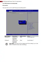
Страница 40: ...lect the proper Operating System BIOS Setting Description Setting Option Effect Windows 8 X Allows user to choose the proper OS Enter Use Windows 8 X Windows 7 Allows user to choose the proper OS Enter Use Windows 7 Important The device will be shipped with OS according to your order BIOS OS Selection menu varies accordingly ...

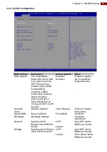
Страница 41: ...OMs that do not support UEFI to still be used Enabled Disabled Enable or disable the Compatibility Support Module GetaA20 Active Activate GetaA20 Upon Request Enable or disable this function Option ROM Messages Receiving ROM Messages Settings Force BIOS Set ROM messages parameters Network Specifies which Network option ROM is booted UEFI Only UEFI option ROMs are booted Legacy Storage Specifies wh...

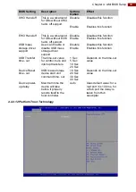
Страница 42: ...ices other than the network storage or video UEFI Only UEFI option ROMs are booted Legacy Only Legacy option ROMs are booted 4 2 2 11 USB Configuration BIOS Setting Description Setting Option Effect Legacy USB Support User can enable or disable USB port Disable Will keep USB devices available only for EFI applications Enable Enable all the USB devices USB 3 0 Support User can enable or disable USB...

Страница 43: ...s storage driver support Disable Disables this function Enable Enables this function USB Transfer time out The time out value for control bulk and interrupt transfers 1 Sec 5 Sec 10 Sec 20 Sec Depends on the time out value Device Reset time out USB mass storage device start unit command time out 10 Sec 20 Sec 30 Sec 40 Sec Depends on the time out value Device power up delay Maximum time the device...

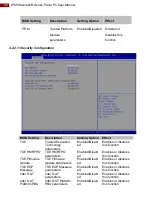
Страница 44: ...d Disabl ed Enables or disables this function TXE HMRFPO TXE HMRFPO parameters Enabled Disabl ed Enables or disables this function TXE Firmware Update TXE Firmware Update parameters Enabled Disabl ed Enables or disables this function TXE EOP Message TXE EOP Message parameters Enabled Disabl ed Enables or disables this function Intel AT Intel AT parameters Enabled Disabl ed Enables or disables this...

Страница 45: ...ables Disables this function Restore AC Power Loss This function allows to set up booting options after a power failure Power on Power off Boot automatically after a power failure Serial IRQ Mode When working with personal computer hardware installing and removing devices the system relies on interrupt requests Interrupt request Continuous Allow user to set up desired IRQ Mode ...

Страница 46: ...ministrator password user password and HDD security configuration BIOS Setting Description Setting Option Effect Administrator Password Displays whether or not an administrator password has been set Enter Enter password User Password Display whether or not a user Password has been set Enter Enter password ...

Страница 47: ... to load the operating system BIOS Setting Description Setting Option Effect Setup Prompt Timeout Allows user to configure the number of seconds to stay in BIOS setup prompt screen Enter Set the prompt timeout Boot NumLock State Enables or disables NumLock feature on the numeric keypad of the keyboard after the POST Default On On Remains On Off Remains OFF Quite Boot Determines if POST message or ...

Страница 48: ...y UEFI option is booted Boot Option 1 6 Specifies the overall boot order from the available devices Ex Boot Option 1 hard drive Hard drive as the first priority USB Key Drive BBS Priorities USB Key Drive BBS Priorities Enter Open sub menu Hard Disk Drive BBS Priorities Hard Disk Drive BBS Priorities Enter Open sub menu Network Drive BBS Priorities Network Drive BBS Priorities Enter Open sub menu 4...

Страница 49: ...Enter YES Saves the changes Enter NO Return to the BIOS Setup Main Menu Save Changes Save changes done so far to any of the setup options Enter YES Saves the changes Enter NO Return to the BIOS Setup Main Menu Discard Changes Discard changes done so far to any of the setup options Enter YES Saves the changes Enter NO Return to the BIOS Setup Main Menu Restore Default Restore load default values fo...

Страница 50: ...y procedure Plug in the AC adapter to Bay Trail series computer Make sure the computer stays plugged in to power source during the recovery process Turn on the computer and when the boot screen shows up press the F6 to initiate the Recovery Wizard The following screen shows the Recovery Wizard Click Recovery button to continue A warning message about data loss will show up Make sure the data is ba...

Страница 51: ...lation This chapter provides guideline to driver installations 5 1 Installing Chipset Driver Step 1 Insert the CD that comes with the motherboard Open the file document Chipset Driver and click infinst_auto exe to install driver Step 2 Click Next to continue ...

Страница 52: ...Manual Step 3 Click Yes to agree the license terms Step 4 Click Next to install the driver Step 5 Software setup progress window will appear click Next to continue Step 6 Click Yes I want to restart this computer now to finish the installation ...

Страница 53: ...ss Step 3 Carefully read the license terms and click Yes to agree Step 4 Check Readme file information and click Next to install driver Step 5 Click Next to continue Step 6 Windows Security window will appear click Install this driver software anyway to continue Step 7 Setup Progress window will appear click Next to continue the installation Step 8 Setup is complete click Yes I want to restart thi...

Страница 54: ...exe to install the driver Step 2 Welcome to the setup program window will appear click Next to start the installation Step 3 Carefully read the License Agreement terms and click Yes to agree Step 4 Setup progress will appear please wait for the operations to be performed then click Next to continue Step 5 The installation is complete click Yes I want to restart this computer now to finish and rest...

Страница 55: ...driver Step 2 Welcome to the setup program window will appear click Next to start the installation Step 3 Carefully read the license terms and click Yes to agree Step 4 Confirmation window will appear click Next to continue the driver installation Step 5 Please wait while the product is being installed Step 6 The installation is complete click Finish to complete the installation and restart the co...

Страница 56: ...l appear click Next to install the driver Step 4 In the program maintenance window you will see two options available Remove is to remove Intel Networks Connections from your computer and Modify is to make any changes Choose Modify to continue Step 5 In the Setup Options window choose Intel PRO Set for Windows Device Manger Intel Network Connections SNMP Agent and Advanced Network Services Step 6 ...

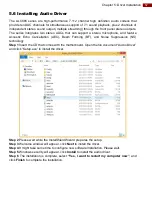
Страница 57: ...Echo Cancellation AEC Beam Forming BF and Noise Suppression NS technology Step 1 Insert the CD that comes with the motherboard Open the file document Audio Driver and click Setup exe to install the driver Step 2 Please wait while the InstalShield Wizard prepares the setup Step 3 Welcome window will appear click Next to install the driver Step 4 It might take some time to configure new software ins...

Страница 58: ...reen permanent staining or discoloration may occur 6 2 Basic Troubleshooting Problem Solution There is a black dot or dead pixel dot on the screen A missing pixel does not constitute an out of spec defective product Cannot turn power on Turn off the power supply and check that the AC cord or DC cord are securely inserted After checking turn on the power supply again There are spots on the screen T...

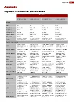
Страница 59: ...tek HD codec Expansion 1 x mPCIe slot for half size Wi Fi module 1 x mPCIe slot for half size Wi Fi module 1 x mPCIe slot for half size Wi Fi module 1 x mPCIe slot for half size Wi Fi module Network Intel Ethernet Controller I210 AT Intel Ethernet Controller I210 AT Intel Ethernet Controller I210 AT Intel Ethernet Controller I210 AT Operating System Windows 10 IoT Enterprise Windows 10 IoT Enterpr...

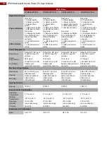
Страница 60: ...or for status Power Management Power Input Default 12V DC input 9 36V DC input for optional Default 12V DC input 9 36V DC input for optional Default 12V DC input 9 36V DC input for optional Default 12V DC input 9 36V DC input for optional Power Consumption 26 W typ 30 W typ 36 W typ 50 W typ AC Adapter 100 240V AC to DC Adapter with waterproof connector 100 240V AC to DC Adapter with waterproof co...

Страница 61: ...SDK and Utilities for the IP65 Stainless B Series Panel PC Item File Type Description 1 SDK Watchdog SDK 2 Utility Watchdog Utility To find the Drivers and SDK please refer to the Driver CD that comes in the package or contact us Also you can download drivers from Winmate Download Center ...

Страница 62: ...________________________ ______________________________________________________________________________ ______________________________________________________________________________ ______________________________________________________________________________ ______________________________________________________________________________ ___________________________________________________________...

Страница 63: ...________________________ ______________________________________________________________________________ ______________________________________________________________________________ ______________________________________________________________________________ ______________________________________________________________________________ ___________________________________________________________...

Страница 64: ...Winmate Inc 9F No 111 6 Shing De Rd San Chung District New Taipei City 24158 Taiwan R O C www winmate com Copyright Winmate Inc All rights reserved ...

Отзывы: