English
Installation and operating instructions Wilo-SiFire System
33
6.2 Description of the product
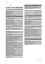
6.2.1 The booster - See fig. 3 – Position:
1 Gate valve
2 Connection for local sprinkler
3 Double pressure switch circuit main pump
4 Non-return valve
5 Flexible vibration-damping sleeves for diesel
pump
6 Connection for recirculation circuit with dia-
phragm
7 Divergent cone on discharge side main pump
8 Pump/motor coupling with spacer
9 Main pump electric/diesel motor
10 Coupling guard
11 Main pump control panel
12 Jockey pump control panel
13 Discharge manifold
14 Connection for setting of flow meter option
15 Fuel tank (for diesel pump)
16 Connection for priming circuit of main pump
17 Main pump
18 Jockey pump
19 Tank for fuel leakages
20 Fuel tank vent valve
21 Fuel level gauge
22 Drain for cleaning of deposit in fuel tank
23 Drain for cleaning of deposit in tank for fuel
leakage
24 Fuel filler cap
25 Connection for motor return pipe
26 Connection for fuel supply to the motor
27 Level gauge for fuel
6.2.2 Control box
• Ensure complete automatic operations of each
pump and associated functions
• Waterproof, protection class IP 54.
6.3 Function of the product
The operational logic for the fire extinguishing
unit is based on the cascade calibration of the
pressure switches for pump starting. The jockey
pump of pressure boosting is the first to start and
maintains the system full of water and under pres-
sure. It starts when the pressure drops in the sys-
tem. Start and stop control is set up via the
suitably calibrated pressure switch.
When a larger quantity of water is requested, due
to the opening of one or more circuits or due to a
broken sprinkler, pressure decreases in the sys-
tem. This drives the main pump to start.
For systems with more than one pump, if the main
electric pump does not start, due to electricity
problems for example, the drop in pressure will
activate the standby pump pressure switch which
starts the diesel engine. In some cases, two or
more electric pumps could be used.
Once the sprinkler circuit or the gate valve that
supply the sprinkler system is closed, the system
reaches the maintaining pressure of the installa-
tion; it will be necessary to press the –Stop– but-
tons on panels to stop the main pump and standby
pump. The jockey pump is automatically stopped.
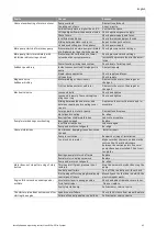
Æ discharge of main pump
Æ Accessories
Æ Manifolds
DN32
DN50
DN65
DN40
DN65
DN65
DN50
DN65
DN80
DN65
DN80
DN100
DN80
DN100
DN125
DN100
DN125
DN150
DN125
DN150
DN200
Содержание SiFire EN 100/200-205-45 E
Страница 2: ...Fig 1 Fig 2a A 2 2 E B C D ...
Страница 3: ...Fig 2b Fig 3 21 25 26 13 11 12 19 15 22 27 20 24 23 2 1 14 4 16 7 5 6 10 18 17 9 9 10 8 3 ...
Страница 4: ...Fig 4 Fig 5 ...
Страница 5: ...Fig 6a 3 5 D D 4 D 2 3 C min max 1 8 m s Fig 6b min 3 5 D D 4 D max 2 m 2 3 C max 1 8 m s ...
Страница 6: ...Fig 7 Fig 8 max 3 2 m min A B C D 2 4 5 6 3 8 7 1 ...
Страница 7: ...Fig 9a Fig 9b A B C D 800 800 800 ...
Страница 8: ...Fig 1a Fig 9a variant Fig 9b variant A B C D 800 800 800 ...
Страница 9: ...Fig 10 Fig 11 1 2 1 2 1 ...
Страница 10: ......
Страница 108: ...Български 100 WILO SE 01 2013 3LRQHHULQJ IRU RX 2 6 1RUWNLUFKHQVWUD H RUWPXQG HUPDQ 7 ZLOR ZLOR FRP ZZZ ZLOR FRP ...

