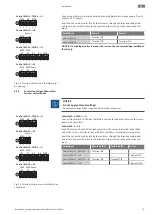
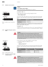
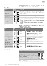
background image

en

Maintenance and repair

32

WILO SE 2020-05

9.3

Shut-down

To decommission the pumps, switch off the pumps and switchgear at the main switch.
The switchgear is ready for operation at any time. Adhere to the following points during
the standstill period:

ƒ

Ambient temperature: -30 … +60 °C

ƒ

Max. humidity: 50 %, non-condensing

System is prepared for decommissioning, e.g. inlet in pump chamber closed.

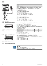
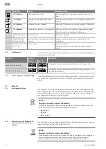
1. Press the “stop” button.

⇒ The “Pump operation” LED goes out.

⇒ LED “auto” flashes.

2. Turn main switch to the “0/OFF” position.

⇒ The “on” LED goes out.

⇒ The “auto” LED goes out.

3. Secure the main switch against being activated by unauthorised persons (e.g. lock

main switch)

▶ Switchgear switched off.

9.4

Removal

DANGER
Risk of death due to electrocution!

Improper conduct when carrying out electrical work can lead to death due to electric
shock! Electrical work must be carried out by a qualified electrician in accordance
with the locally applicable regulations.

Decommissioning performed.

Mains connection is switched so that it is voltage-free and safeguarded against
being activated by unauthorised persons.

The power connection for fault and run signals is switched so that it is voltage-free
and safeguarded against being activated by unauthorised persons.

1. Open the switchgear.

2. Disconnect all connection cables and pull them out through the threaded cable

connection.

3. Close off the ends of the connection cables watertight.

4. Seal threaded cable connections watertight.

5. Support the switchgear (e.g. get a second person to help).

6. Loosen the switchgear fastening screws and remove the switchgear from the

structure.

▶ Switchgear removed. Observe the following for storage!

10

Maintenance and repair

DANGER
Risk of death due to electrocution!

Improper conduct when carrying out electrical work can lead to death due to electric
shock! Electrical work must be carried out by a qualified electrician in accordance
with the locally applicable regulations.

NOTICE
Unauthorised work or structural changes are prohibited!

Only maintenance and repair work described in this manual may be carried out. All
other works and any alterations to the construction may only be carried out by the
manufacturer.

Содержание Control MS-L 2x8A-T4-DOL-X

Страница 1: ...Pioneering for You Wilo Control MS L 2552612 Ed 01 2020 05 en Installation and operating instructions...

Страница 2: ......

Страница 3: ...3 M L N PE N WSK 1 230V 50 60Hz 1 L N ON OFF DrainAlarm ON L N 1 230V 50Hz U V W L N 1 230V 50Hz 120 60 0 Seconds ON 100 K DIP 1 2 3 4 5 6 7 8 PE SSM 1 2 3 7 8 9 4 5 6 GL WSK HW T1 1 3 5 13 A1 2 4 6...

Страница 4: ...Hz 3 M PE WSK 1 230V 50 60Hz 1 L N ON OFF DrainAlarm ON L N 1 230V 50Hz U V W L N 1 230V 50Hz 1 2 3 4 1 2 3 4 120 60 0 Seconds ON 100 K DIP 1 2 3 4 5 6 7 8 PE SSM 1 2 3 7 8 9 4 5 6 GL WSK HW T1 1 3 5...

Страница 5: ...F NW21 NW22 L N 1 230V 50Hz U bk bn V W N L L1 L2 L3 PE 3 400V 50 60Hz L1 L L2 N PE 1 230V 50 60Hz 1 230V 50Hz 30 15 0 Seconds ON 100 K DIP 1 2 3 4 5 6 7 PE SSM 1 2 5 7 8 9 6 WSK T1 1 3 5 13 A1 2 4 6...

Страница 6: ...5 6 7 SSM Alarm GL WSK P2 WSK P1 SL 10 16 15 14 13 12 11 9 8 7 6 5 4 3 2 1 HW T1 1 3 5 13 A1 2 4 6 14 A2 T2 T3 L1 L2 L3 NO L1 L2 L3 N WSK M 3 WSK M 1 T1 1 3 5 13 A1 2 4 6 14 A2 T2 T3 L1 L2 L3 NO ON DI...

Страница 7: ...conds ON 100 K DIP 1 2 3 4 5 6 7 SSM Alarm GL WSK P2 WSK P1 SL 10 16 15 14 13 12 11 9 8 7 6 5 4 3 2 1 HW T1 1 3 5 13 A1 2 4 6 14 A2 T2 T3 L1 L2 L3 NO L1 L2 L3 N WSK M 3 WSK M 1 T1 1 3 5 13 A1 2 4 6 14...

Страница 8: ...2 L N 1 230V 50Hz U bk bn V W 30 15 0 Seconds ON 100 K DIP 1 2 3 4 5 6 7 SSM Alarm WSK P2 Sensor ln WSK P1 16 15 14 13 12 11 10 9 4 3 2 1 T1 1 3 5 13 A1 2 4 6 14 A2 T2 T3 L1 L2 L3 NO WSK M 3 WSK M 1 U...

Страница 9: ...6 Type key 15 4 7 Operation on electronic start up controllers 16 4 8 Installation in potentially explosive atmospheres 16 4 9 Scope of delivery 16 4 10 Accessories 16 5 Transportation and storage 16...

Страница 10: ...nance tasks 33 11 Faults causes and remedies 33 11 1 Operator responsibilities 33 11 2 Fault indication 33 11 3 Fault acknowledgement 33 11 4 Error messages 33 11 5 Fault memory 34 11 6 Further steps...

Страница 11: ...ny warranty or liability in the following cases Inadequate configuration due to inadequate or incorrect instructions by the operator or the client Non compliance with these instructions Improper use I...

Страница 12: ...st carry out the electrical work Installation dismantling The technician must be trained in the use of the necessary tools and fixation materials for the relevant construction site Operation control O...

Страница 13: ...cturer may be used for maintenance and repairs Use of parts other than the original parts releases the manufacturer from any liabil ity 2 8 Operator responsibilities Provide installation and operating...

Страница 14: ...level is detected by a separate float switch Control MS L LS The level is detected via two switching points by a rod float sensor 4 20 mA signal The high water level is detected by a separate switchin...

Страница 15: ...ad Minimum 12 VDC 10 mA Maximum 250 VAC 1 A 4 5 Functions The switchgear is equipped with the following functions All functions are switched off at the factory The functions must be switched on as req...

Страница 16: ...g instructions 4 10 Accessories Float switch for drainage and sewage Signal lamp Flash light Horn 5 Transportation and storage 5 1 Delivery After receiving the shipment check it immediately for defect...

Страница 17: ...d length for the routing type chosen Seal unused threaded cable glands Ensure that the following ambient conditions are adhered to Ambient operating temperature 30 60 C Relative humidity 40 50 Max rel...

Страница 18: ...cting the high water level No separate float switch is required If there is an alarm a forced switch on of all pumps occurs 6 5 Electrical connection DANGER Risk of death due to electrocution Improper...

Страница 19: ...r 2 Motor contactor 3 Terminal strip Sensors 4 Terminal strip Earth PE 5 Potentiometer for follow up time 6 Slot 9 V rechargeable battery 7 Terminal strip Mains connection 8 DIP switch 1 9 DIP switch...

Страница 20: ...minal strip Earth 7 Terminal strip Mains connection 8 DIP switch 1 NOTICE Install two cable bridges on the mains terminal strip Terminal 1 2 and ter minal 3 4 Cable 3 core Terminals 4 T2 L N N Connect...

Страница 21: ...7 Terminal strip Mains connection 8 DIP switch 1 NOTICE Do not install any cable bridges on the mains terminal strip Cable 5 core Terminals 1 L1 2 L2 3 L3 4 N Connect the protective earth conductor P...

Страница 22: ...the connected pump Set rated current according to rating plate ON DIP 1 2 3 4 5 6 7 8 Fig 9 DIP switch 1 Adjust motor current mon itoring Set rated current via DIPs 1 5 on DIP switch 1 Minimum rated...

Страница 23: ...ol device NOTICE Do not apply external voltage An external voltage which is applied destroys the component GL WSK P2 WSK P1 SL 10 9 8 7 6 5 4 3 2 1 HW HW GL WSK 6 5 4 3 2 1 3 3 Control MS L1 MS L O WS...

Страница 24: ...tage is also present at the terminals when the main switch is switched off There is a risk of fatal injury The power supply must be disconnected from its source before commencing any work Electrical w...

Страница 25: ...s Follow up time Adjustable switching points for pump ON and high water Key available not available The switching points can be selected from eight sets of parameters for the respective lifting unit 6...

Страница 26: ...5 Follow up time The follow up time defines the time between the float switch OFF signal and the pump being deactivated by the switchgear Adjust the follow up time continuously at the potentiometer 12...

Страница 27: ...of pump 1 Bottom row current status of pump 2 Display LED LED colour Description MS L1 MS L2 Mains connection Green LED lights up Mains voltage and control voltage are on Automatic mode Green LED flas...

Страница 28: ...evel has been reached both pumps are switched on forced switch on The high water LED displays an alarm signal Additionally the internal buzzer can emit an audible alarm signal Furthermore the output f...

Страница 29: ...in potentially explosive areas The switchgear does not have its own explosion protection class and must always be installed outside of potentially explosive areas The connection must be made by a qual...

Страница 30: ...argeable battery again or by connecting the power supply By inserting a rechargeable battery a mains independent alarm signal can be issued in the case of a power failure An audible constant tone is e...

Страница 31: ...Automatic mode switched on The Pump operation LED shows the current status of the pump 8 8 During operation Make sure the following points are observed during operation Keep the switchgear closed and...

Страница 32: ...ed so that it is voltage free and safeguarded against being activated by unauthorised persons The power connection for fault and run signals is switched so that it is voltage free and safeguarded agai...

Страница 33: ...locally applicable accident prevention and safety regulations of trade asso ciations Make sure that the personnel has had the corresponding training for the specified work Train the personnel on how t...

Страница 34: ...the Stop and manual mode buttons for longer approx 1 s at the same time pump 1 11 6 Further steps for troubleshooting If the points listed here do not rectify the fault please contact customer servic...

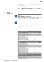
Страница 35: ...ching frequency of the motor must not be exceeded NOTICE Depending on the system impedance and the maximum connections hour of the connected consumers voltage fluctuations and or drops may occur When...

Страница 36: ...en Appendix 36 WILO SE 2020 05 3 400 V 4 pole direct starting Power in kW System impedance in ohm Connections h 3 0 0 2090 6 3 0 0 1380 24 3 0 0 1240 30 4 0 0 1480 6 4 0 0 0830 24 4 0 0 0740 30...

Страница 37: ......

Страница 38: ......

Страница 39: ...ilo it Kazakhstan WILO Central Asia 050002 Almaty T 7 727 312 40 10 info wilo kz Korea WILO Pumps Ltd 20 Gangseo Busan T 82 51 950 8000 wilo wilo co kr Latvia WILO Baltic SIA 1019 Riga T 371 6714 5229...

Страница 40: ...Pioneering for You WILO SE Nortkirchenstr 100 44263 Dortmund Germany T 49 0 231 4102 0 T 49 0 231 4102 7363 wilo wilo com www wilo com...

Отзывы: