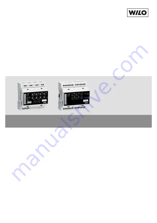
background image

D

Einbau- und Betriebsanleitung

GB

Installation and operating instructions

F

Notice de montage et de mise en service

I

Istruzioni di montaggio, uso e manutenzione

E

Instrucciones de instalación y funcionamiento

Wilo-Control DigiCon/DigiCon-A

2 096 949-Ed.02 

2009-

04-K

o

th

es

!

Содержание Control DigiCon

Страница 1: ...nstallation and operating instructions F Notice de montage et de mise en service I Istruzioni di montaggio uso e manutenzione E Instrucciones de instalaci n y funcionamiento Wilo Control DigiCon DigiC...

Страница 2: ...3 2 1 RSN ON 6 5 pump 1 pump 2 pump 3 pump 4 mode p c p v n c set point address DigiCon 100 0 rs 485 1 1 2 3 4 power rs 485 a b Baud Z rs 232 0 0 0 2 0 0 0 3 0 0 0 4 0 0 0 24 VDC 1 6 19 2 16 14 15 22...

Страница 3: ...ma 0 10V off max min on 24V ssm ebm ma ebm sl 0 10V off max min on 24V ssm ebm ma ebm sl DigiCon A 0 10V disable 0 10V disable sl 1 1 1 ma sl 2 2 2 10 18 1 4 3 22 17 5 11 12 13 7 8 9 10 18 11 12 13 7...

Страница 4: ...Fig 3 set point 0 100 0 V 10 V 0 10 V p v p c m n c min 1 Hmin nmin Hmax nmax Fig 4 DigiCon DigiCon A DigiCon A pump 1 pump 1 pump 3 pump 2 pump 4 pump 2 pump 3 pump 4 1 2 3 4 1 2 3 4 1 2 3 4 1 2 3 4...

Страница 5: ...Fig 5 rs 485 a b DigiCon Nr 1 pump 1 pump 2 pump 3 pump 4 rs 485 a b DigiCon Nr 2 pump 1 pump 2 pump 3 max 1000 m pump 4 rs 485 a b DigiCon Nr 64 pump 1 pump 2 pump 3 pump 4 24V DC RS 485 Fig 6a 1...

Страница 6: ...RSN ON 6 5 pump 1 pump 2 pump 3 pump 4 mode p c p v n c set point address DigiCon 100 0 rs 485 1 1 2 3 4 power rs 485 a b Baud Z rs 232 0 0 0 2 0 0 0 3 0 0 0 4 0 0 0 24 VDC 1 6 19 2 16 14 15 22 21 20...

Страница 7: ...d Betriebsanleitung 3 GB Installation and operating instructions 21 F Notice de montage et de mise en service 40 I Istruzioni di montaggio uso e manutenzione 61 E Instrucciones de instalaci n y funcio...

Страница 8: ......

Страница 9: ...Pumpen zu betrachten 2 Sicherheit DieseBetriebsanleitungenth ltgrundlegendeHinweise diebeiAufstellungund Betrieb zu beachten sind Daher ist diese Betriebsanleitung unbedingt vor Mon tage und Inbetrieb...

Страница 10: ...auszuschlie en Arbeiten an Pumpe n Anlage d rfen nur bei mechanischem Stillstand in spannungslosem Zustand und mit geeigneten Werkzeugen ausgef hrt wer den 3 Transport und Zwischenlagerung Bei Erhalt...

Страница 11: ...g DigiCon A mit zus tz licher Handbedienebene erm glicht die bergeordnete Steuerung von Pumpen die an Schnittstellen Konverter DigiCon und DigiCon Modbus angeschlossen sind Anschlie bare Pumpen 4 Pump...

Страница 12: ...110VDC 0 13ADC 1 Min 12 VDC 10 mA Einzelbetriebsmeldung MA pot freier Schlie er Einzelbetriebsmeldung SL pot freier Schlie er Kontaktbelastung durch Steuereing nge Ext Off pot freier Schlie er 24 VDC...

Страница 13: ...ehan deln Steuerfunktionen beziehen sich auf die Doppelpumpe als gesamtes Aggregat Wilo Control DigiCon Wilo Control DigiCon A Der Schnittstellen Konverter DigiCon wandelt die Schnittstelle PLR Punkt...

Страница 14: ...1 Pos 2 LED ist aus Pumpe ist nicht angemeldet LED leuchtet dauernd gr n Kommunikation Pumpe Schnittstellen Konverter arbeitet fehlerfrei LED leuchtet dauernd rot Kommunikationsst rung zwischen Pumpe...

Страница 15: ...melst rmeldung ssm potenzialfreier Wechsler Fig 2 Pos 7 Kontakt in Ruhestellung Pumpe ist nicht gest rt Kontakt aktiviert Pumpe ist gest rt siehe auch Einbau und Betriebsanleitung der entsprechenden P...

Страница 16: ...ntakt offen Betrieb der Pumpe wird nicht beeinflusst Kontakt geschlossen Pumpe l uft mit Drehzahl des Nacht Absenkbe triebs Steuerkontakt on potenzialfreier Schlie er Fig 2 Pos 13 Kontakt offen Betrie...

Страница 17: ...rkontakte Tab 8 zeigt die Priorit tsreihenfolge der Steuerkontakte und Busbefehle am DigiCon DigiCon A DigiCon DigiCon A Handbedienebene Steuerkontakt off H chste Priorit t Steuerkontakt max Steuerkon...

Страница 18: ...lter mode vorgew hlte Rege lungsart Fig 3 p c 0 Hmin 100 Hmax p v 0 Hmin 100 Hmax n c 0 min Drehzahl 100 max Drehzahl Die Werte Hmin Hmax min Drehzahl und max Drehzahl sind vom Pumpentyp abh n gig Tas...

Страница 19: ...max n c 0V min Drehzahl 10V max Drehzahl Das Signal am Analogein gang 0 10V bersteuert den am Drehknopf set point eingestellten Wert und den Sollwert der ber den Bus RS 485 gesendet wird DIP Schalterb...

Страница 20: ...Wertigkeiten ermittelt und durch Addition des Wertes des leitungsge bundenen Anschlusses an die zugh rigen Klemmen Beispiele Adresse von Pumpe 1 an DigiCon Nr 1 DIP Schalter 000000 0 0 0 Adresse von P...

Страница 21: ...6 22 4 Resultierende Pumpen Adresse Nr der Pumpe Nr des DigiCon Pumpe 1 1 0 0 0 0 0 0 0 Pumpe 2 1 1 Pumpe 3 1 2 Pumpe 4 1 3 Pumpe 1 12 0 0 1 0 1 1 44 Pumpe 2 12 45 Pumpe 3 12 46 Pumpe 4 12 47 Pumpe 1...

Страница 22: ...werden Der Ausgangsstrom des Netzteils h ngt von der Anzahl der anzuschlie enden DigiCons Komponenten ab Die Handbedienebene DigiCon A wird rechts neben dem zugeh rigen Schnitt stellen Konverter Digi...

Страница 23: ...nopf set point Fig 1 Pos 15 den gew nschten Sollwert einstellen Durch Dr cken der Taste Fig 1 Pos 16 werden die Einstellungen an die ange schlossene Pumpe gesendet Die vorangegangenen Schritte k nnen...

Страница 24: ...s Abschlusswiderst nde und Kabelschirm berpr fen Am Display der Pumpe pr fen ob der automatische Verbin dungsaufbau zwischen Pumpe und DigiCon ber die Schnitt stellePLRerfolgtist ImDisplay der Pumpe m...

Страница 25: ...ber die RS 485 Pumpe in der GA einschalten berpr fen ob der Steuerkon takt Ext Off an der Pumpe ge ffnet ist Ext Off an der Pumpe br cken Fehler an der Verkabelung zwi schen Pumpe und DigiCon Kabel b...

Страница 26: ...11 Ersatzteile F r Wilo Control DigiCon und DigiCon A sind keine Ersatzteile verf gbar Im Schadensfall ist das komplette Ger t zu tauschen und die defekte Einheit an den Hersteller zur ckzugeben Techn...

Страница 27: ...of the pumps connected to the interface converter 2 Safety These operating instructions contain basic information which must be adhered to during installation and operation For this reason these oper...

Страница 28: ...electrical current must be eliminated Work on pump s and the unit may only done when they are stationary switched off at the mains and with suitable tools 3 Transport and interim storage Check the pro...

Страница 29: ...tional manual operation level allows the higher ranking control of pumps that are con nected to DigiCon and DigiCon Modbus interface converters Pumps that can be connected 4 pumps single or double Pum...

Страница 30: ...ee changeover contact Max 250 VAC 1 A AC 1 110VDC 0 13ADC 1 Min 12 VDC 10 mA Single operation signal MA potential free normally open contact Single operation signal SL potential free normally open con...

Страница 31: ...nual operation level Installation and operating instructions CD with documentation and details of the PLR protocol DigiCon only 8 pole 2 x 4 plug DigiCon A only RS 485 interface Max cable length 1000...

Страница 32: ...iCon interface converter converts the PLR interface point to point inter face into an RS 485 serial digital interface with bus capability The software protocol is PLR The protocol is described in deta...

Страница 33: ...l lamp Fig 1 item 2 LED is off Pump has not logged on LED lights up green continuously Pump Interface Converter communication working perfectly LED lights up red continuously Communication problem bet...

Страница 34: ...o communication on the RS 485 interface in the last minute LED lights up green continuously Fault free communication on the RS 485 interface within the last minute LED lights up red continuously Commu...

Страница 35: ...nstallation and operating instructions for the pump concerned Single operation signal Master ebm ma potential free normally open contact Fig 2 item 8 Contact is activated parallel to the Single or dou...

Страница 36: ...contact Fig 2 item 12 Contact open Operation of pump is not affected Contact closed Pump running a reduced night mode speed Control contact on potential free normally open contact Fig 2 item 13 Conta...

Страница 37: ...t min Control contact on Bus level 485 PLR Bus command max Bus command min Bus command on Lowest priority Tab 8 DigiCon DigiCon A Mode rotary switch Fig 1 item 14 Rotary switch for setting control mod...

Страница 38: ...tem 18 The signal at the analogue input 0 10V specifies the setpoint for the mode set with the mode rotary switch p c 0V Hmin 10V Hmax p v 0V Hmin 10V Hmax n c 0V min speed 10V max speed The signal at...

Страница 39: ...ponding pumps is determined by adding the signifi cances marked 1 and by adding the value of the hard wired connection to the corresponding terminals Examples Address of pump 1 at DigiCon no 1 DIP swi...

Страница 40: ...t pump address No of the pump No of the DigiCon Pump 1 1 0 0 0 0 0 0 0 Pump 2 1 1 Pump 3 1 2 Pump 4 1 3 Pump 1 12 0 0 1 0 1 1 44 Pump 2 12 45 Pump 3 12 46 Pump 4 12 47 Pump 1 26 0 1 1 0 0 1 100 Pump 2...

Страница 41: ...n the switch cabinet with the corresponding output voltage The output current of the power supply unit depends on the number of DigiCon components to be connected The DigiCon A manual operation level...

Страница 42: ...t the setpoint knob Fig 1 item 15 The settings are sent to the connected pump by pressing the button Fig 1 item 16 The preceding steps can be repeated with different settings for each pump connected t...

Страница 43: ...RS 485 cable check connection termination resistances and cable screen Check on the pump display whether the automatic com munication build up between pump s and DigiCon via the PLR interface has tak...

Страница 44: ...itch on the pump in the BMS Check whether the control contact Ext Off at the pump is open Override Ext Off at the pump Wiring fault between pump and DigiCon Check cable No mains voltage at the pump Re...

Страница 45: ...DigiCon DigiCon A 39 English 11 Spare parts No spare parts available for Wilo Control DigiCon and DigiCon A In the eventofdamage thecompletedevicemust be replacedand the defective unit returned to the...

Страница 46: ...nsignes essentielles qui doivent tre respect es lors du montage et de l utilisation Ainsi il est indispensable que l installateur et l op rateur du mat riel en prennent connaissance avant de proc der...

Страница 47: ...courant lectrique Les travaux sur la ou les pompes doivent uniquement tre effectu s l tat d arr t m canique hors tension et l aide d outils appropri s 3 Transport et entreposage D s r ception v rifie...

Страница 48: ...a com mande sup rieure des pompes raccord es aux convertisseurs d interface DigiCon et DigiCon Modbus Pompes raccordables 4 pompes pompes simples ou doubles Pompes pilotables 2 pompes pompes simples o...

Страница 49: ...ax 250 VAC 1 A AC 1 110VDC 0 13ADC 1 Min 12 VDC 10 mA Report de d faut collectif Inverseur contact sec Report de marche individuel MA Contact sec fermeture Report de marche individuel SL Contact sec f...

Страница 50: ...t de mise en service CD avec documentation et d tails du protocole PLR DigiCon uniquement Fiche 8 p les 2 x 4 DigiCon A uniquement Interface RS 485 Longueur de c ble max 1000 m Section de c ble min 2x...

Страница 51: ...giCon Wilo Control DigiCon A Le convertisseur d interface DigiCon convertit l interface PLR interface point par point en une interface RS 485 s rielle num rique et compatible bus Le protocole logiciel...

Страница 52: ...giCon non pr sente T moin lumineux Communication pompe fig 1 pos 2 DEL teinte La pompe n est pas activ e La DEL est allum e en vert en continu La communication Pompe convertisseur d interface fonction...

Страница 53: ...a pompe double sl est en ser vice T moin lumineux Communication bus fig 1 pos 6 DEL teinte pas de communication sur l interface RS 485 au cours de la derni re minute La DEL est allum e en vert en cont...

Страница 54: ...de montage et de mise en service de la pompe cor respondante Report de marche individuel Ma tre ebm ma Contact sec fermeture fig 2 pos 8 Contact est activ parall lement au t moin lumineux Marche pomp...

Страница 55: ...Le fonctionnement de la pompe n est pas affect Contact ferm La pompe fonctionne selon la vitesse de rotation du fonctionnement ralenti de nuit Contact de commande on Contact sec fermeture fig 2 pos 13...

Страница 56: ...contacts de commande et des instructions de bus sur le DigiCon DigiCon A DigiCon DigiCon A Commande manuelle Contact de commande off Priorit maximale Contact de commande max Contact de commande min Co...

Страница 57: ...nsi gne pour le type de r gulation pr s lectionn avec le com mutateur rotatif mode fig 3 p c 0 Hmin 100 Hmax p v 0 Hmin 100 Hmax n c 0 vitesse de rota tion min 100 vitesse de rota tion max Les valeurs...

Страница 58: ...esse de rota tion min 10 V vitesse de rota tion max Le signal l entr e analogi que 0 10 V crase la valeur r gl e sur le bouton tournant set point ainsi que la valeur de consigne envoy e sur le bus RS...

Страница 59: ...est d termin e par l addition des valen ces dot es de 1 et par l addition de la valeur du raccordement c bl aux bor nes correspondantes Exemples adresse de la pompe 1 sur le DigiCon N 1 commutateur DI...

Страница 60: ...de pompe obtenue N de la pompe N du DigiCon Pompe 1 1 0 0 0 0 0 0 0 Pompe 2 1 1 Pompe 3 1 2 Pompe 4 1 3 Pompe 1 12 0 0 1 0 1 1 44 Pompe 2 12 45 Pompe 3 12 46 Pompe 4 12 47 Pompe 1 26 0 1 1 0 0 1 100...

Страница 61: ...ler dans l armoire de commande un bloc d alimentation s par dot de la tension de sortie appropri e Le courant de sortie du bloc d alimentation d pend du nombre de DigiCons composants raccorder La comm...

Страница 62: ...ig 1 pos 14 le type de r gulation souhait Sur le bouton tournant set point fig 1 pos 15 r gler la valeur de consigne souhait e Une pression sur la touche fig 1 pos 16 permet d envoyer les r glages la...

Страница 63: ...uer les travaux d entretien et de r paration AVERTISSEMENT Risque de choc lectrique Exclure tout danger li au courant lectrique Pour tous les travaux d entretien et de r paration il convient de commut...

Страница 64: ...mpe doit afficher le symbole de com munication Fl che double Le c ble entre le DigiCon et la pompe est coup r parer le c ble V rifier le module IF Toutes les pompes raccord e un DigiCon ne suit pas le...

Страница 65: ...er la pompe sur le GTB V rifier si le contact de com mande Ext Off est ouvert sur la pompe Ponter Ext Off sur la pompe D faut de c blage entre la pompe et le DigiCon V rifier le c ble Pas de tension d...

Страница 66: ...de rechange Pour le Wilo Control DigiCon et le DigiCon A aucune pi ce de rechange n est n cessaire En cas de panne il faut remplacer l appareil complet et retourner l unit d fec tueuse au fabricant So...

Страница 67: ...ntaggio uso e manutenzione per le pompe collegate al convertitore di porta 2 Sicurezza Le presenti istruzioni contengono informazioni fondamentali ai fini del corretto montaggio e uso del prodotto Dev...

Страница 68: ...cludere pericoli causati da corrente elettrica L esecuzione di qualsiasi lavoro sulla e pompa e consentito solo in stato di arresto meccanico in stato esente da tensione e con utensili adatti 3 Traspo...

Страница 69: ...L ampliamento DigiCon A con comando manuale supplementare permette il con trollo di gerarchia superiore delle pompe collegate ai convertitori di porta DigiCon e DigiCon Modbus Pompe collegabili 4 pomp...

Страница 70: ...rferenze 61000 6 3 Immunit da interferenze 61000 6 2 Carico del contatto dei contatti di segnalazione Segnale di blocco cumulativo contatto di scambio libero da pot Max 250 VAC 1 A AC 1 110VDC 0 13ADC...

Страница 71: ...gli del protocollo PLR solo DigiCon a 8 poli 2 x 4 spina solo DigiCon A Ingresso di comando Analogico In 0 10 V Resistenza dell ingresso 200 k Protezione contro sovraccarico 48 VDC Interfaccia PLR Max...

Страница 72: ...itore di porta DigiCon trasforma l interfaccia PLR interfaccia punto a punto in una interfaccia bus RS 485 seriale digi tale Il protocollo software PLR Il proto collo descritto in dettaglio nel CD in...

Страница 73: ...Il LED spento la pompa non registrata Il LED verde costantemente illuminato la comunicazione Pompe Convertitore di porta fun ziona senza disturbi Il LED rosso costantemente illuminato la comunicazione...

Страница 74: ...le fig 2 pos 7 Contatto in posizione di risposo la pompa non in blocco Contatto attivato pompa in blocco vedi anche Istruzioni di montag gio uso e manutenzione per la relativa pompa Segnale di funzion...

Страница 75: ...tenziale fig 2 pos 12 Contatto aperto il funzionamento della pompa non viene influen zato Contatto chiuso la pompa in funzionamento a regime ridotto funzionamento notturno Contatto di comando on conta...

Страница 76: ...di priorit dei contatti di comando e dei comandi bus su DigiCon DigiCon A DigiCon DigiCon A Comando manuale Contatto di comando off Priorit massima Contatto di comando max Contatto di comando min Cont...

Страница 77: ...mpostazione del valore nomi nale per il modo di regolazione preselezionato con l interrut tore rotante mode fig 3 p c 0 Hmin 100 Hmax p v 0 Hmin 100 Hmax n c 0 numero di giri min 100 numero di giri ma...

Страница 78: ...di giri min 10 V numero di giri max Il segnale sull ingresso ana logico 0 10 V supera il valore impostato dalla manopola set point e il valore nominale che viene inviato mediante il Bus RS 485 Blocco...

Страница 79: ...ve pompe viene determinato sommando i valori contras segnati con 1 e sommando il valore del raccordo collegato al cavo sul rispet tivo morsetto Esempio Indirizzo della pompa 1 su DigiCon n 1 interrutt...

Страница 80: ...o pompa risultante N della pompa N del DigiCon Pompa 1 1 0 0 0 0 0 0 0 Pompa 2 1 1 Pompa 3 1 2 Pompa 4 1 3 Pompa 1 12 0 0 1 0 1 1 44 Pompa 2 12 45 Pompa 3 12 46 Pompa 4 12 47 Pompa 1 26 0 1 1 0 0 1 10...

Страница 81: ...installato un alimentatore separato con tensione in uscita corrispondente La tensione in uscita dell alimentatore dipende dal numero di DigiCons compo nenti da collegare Il comando manuale DigiCon A...

Страница 82: ...erato con la manopola set point fig 1 pos 15 Premendo il tasto fig 1 pos 16 vengono inviate le impostazioni alle pompe collegate I passi precedenti possono essere ripetuti utilizzando diverse impo sta...

Страница 83: ...one solo da personale tecnico qualificato AVVISO Pericolo di folgorazione Prendere le misure di protezione necessaire per escludere pericoli causati da corrente elettrica Per tutti i lavori di manuten...

Страница 84: ...play della pompa deve esserevisualizzatoilsimbolodi comunicazione Doppia frec cia IlcavotraDigiConelapompa interrotto riparare il cavo Verificare il modulo IF Tutte le pompe su un DigiCon non seguono...

Страница 85: ...a nel BMS Controllare se il contatto di comando Ext Off sulla pompa aperto Ponticellare Ext Off sulla pompa Errore nel cablaggio tra la pompa e DigiCon Controllare il cavo Non presente nessuna ten sio...

Страница 86: ...009 11 Parti di ricambio Per Wilo Control DigiCon e DigiCon A non sono disponibili parti di ricambio In caso di guasto si deve sostituire tutto l apparecchio e restituire l unit guasta al costruttore...

Страница 87: ...manual contiene indicaciones b sicas que deber n tenerse en cuenta durante la instalaci n y uso del aparato Por este motivo el instalador y el ope rador responsables deber n leerlo antes de montar y p...

Страница 88: ...ualquier trabajo que deba efectuarse en la s bomba s s lo se realizar durante la parada mec nica de sta s en estado de desconexi n el ctrica y con las herramientas adecuadas 3 Transporte y almacenamie...

Страница 89: ...s La ampliaci n DigiCon A con nivel de mando manual adicional permite el control a un nivel superior de las bombas que est n conectadas a convertidores de interface DigiCon y DigiCon Modbus Bombas con...

Страница 90: ...stencia a interferencias EN 61000 6 2 Carga de contacto conts de indicaci n Indicaci n general de aver a Contacto de conmut libre de tensi n M x 250 VAC 1 A AC 1 110VDC 0 13ADC 1 Min 12 VDC 10 mA Indi...

Страница 91: ...ntaci n y detalles del protocolo PLR s lo DigiCon Enchufe de 8 polos 2 x 4 s lo DigiCon A Resistencia de entrada 200 k Protecci n frente a sobretensi n 48 VDC Interface PLR Longitud de cable m x 200 m...

Страница 92: ...n con vierte la interface PLR interface punto a punto en una interface serial digital con capacidad de conexi n bus RS 485 El pro tocolo de software es PLR El protocolo es descrito en detalle en el CD...

Страница 93: ...Fig 1 pos 2 LED desconectado Bomba no registrada LEDcontinuamenteencendido con luz verde La comunicaci n Bomba Convertidor de interface funciona sin fallos LEDcontinuamenteencendido con luz roja Aver...

Страница 94: ...tensi n Fig 2 pos 7 Contacto en posici n de reposo La bomba no est averiada Contacto activado Bombaaveriada v ansetambi nlasinstrucciones de instalaci n y funcionamiento de la bomba correspondiente In...

Страница 95: ...e de tensi n Fig 2 pos 12 Contacto abierto No influye en el funcionamiento de la bomba Contacto cerrado Bomba en marcha a velocidad de funcionamiento de reducci n nocturno Contacto de control on de co...

Страница 96: ...e bus min Orden de bus on Prioridad m nima Tab 8 DigiCon DigiCon A Conmutador giratorio mode Fig 1 pos 14 Conmutador giratorio para el ajuste del modo de regulaci n p c para una presi n dife rencial c...

Страница 97: ...cada bomba 0 10 V entrada anal gica 0 10 V activada disable entrada anal gica 0 10 V bloqueada Entrada anal gica 0 10 V Fig 2 pos 18 La se al en la entrada anal gi ca 0 10 V especifica el valor de co...

Страница 98: ...bomba 1 a DigiCon n 1 interruptor DIP 000000 0 0 0 Direcci n de bomba 4 a DigiCon n 1 interruptor DIP 000000 0 3 3 Direcci n de bomba 3 a DigiCon n 12 interruptor DIP 001011 32 8 4 2 46 Bloque de int...

Страница 99: ...25 32 4 24 16 5 23 8 6 22 4 Direcci n resultante de la bomba N de bomba N del DigiCon Bomba 1 1 0 0 0 0 0 0 0 Bomba 2 1 1 Bomba 3 1 2 Bomba 4 1 3 Bomba 1 12 0 0 1 0 1 1 44 Bomba 2 12 45 Bomba 3 12 46...

Страница 100: ...correspondiente tensi n de salida La intensidad de salida de la fuente de alimentaci n depende del n mero de uni dades DigiCon componentes a conectar El nivel de mando manual DigiCon A se monta a la d...

Страница 101: ...giCon Ajustar en el interruptor mode Fig 1 pos 14 el modo de regulaci n deseado Ajustar en el bot n giratorio set point Fig 1 pos 15 el valor de consigna deseado Al pulsar la tecla Fig 1 pos 16 se tra...

Страница 102: ...las resistencias de cie rre y el apantallamiento del cable Comprobar en la pantalla de la bomba si se ha producido el establecimiento autom tico de la conexi n entre la bomba y el DigiCon a trav s de...

Страница 103: ...la bomba en la GTC Comprobar si est abierto el contacto de control Ext Off de la bomba Puentear el contacto Ext Off en la bomba Fallo en el cableado entre la bomba y el DigiCon Comprobar el cable No...

Страница 104: ...uestos Para Wilo Control DigiCon y DigiCon A no hay repuestos disponibles En caso de da os hay que cambiar el aparato completo y remitir al fabricante la unidad defectuosa Queda reservado el derecho a...

Страница 105: ...ungary WILO Magyarorsz g Kft 2045 T r kb lint Budapest T 36 23 889500 wilo wilo hu Ireland WILO Engineering Ltd Limerick T 353 61 227566 sales wilo ie Italy WILO Italia s r l 20068 Peschiera Borromeo...

Страница 106: ...1 4102 7900 T 01805 W I L O K D 9 4 5 6 5 3 F 0231 4102 7126 kundendienst wilo com Erreichbar Mo Fr von 7 17 Uhr Wochenende und feier tags 9 14 Uhr elektroni sche Bereitschaft mit R ckruf Garantie Kun...

Отзывы: