background image

430 Ink Jet Printer Service and Maintenance Manual

8

Issue 2

Part No. 306-0430-102

To remove trapped air, proceed as follows:

Remove the front and rear covers from the printhead.

Slacken the jet valve (V11) screws.

Place tissue paper around the printhead and jet valve to absorb solvent when the priming procedure

commences.

WARNING - HANDLING CLEANING AGENT

The cleaning agent is irritating to the eyes and respiratory system. To prevent personal

injury when handling this substance:

Always wear protective rubber gloves and clothing.

Always wear goggles with side-shields or a face mask. It is also advisable to wear safety

glasses when carrying out maintenance.

Apply barrier hand cream before handling ink.

If cleaning agent contaminates the skin, rinse off with running water for at least

15 minutes.

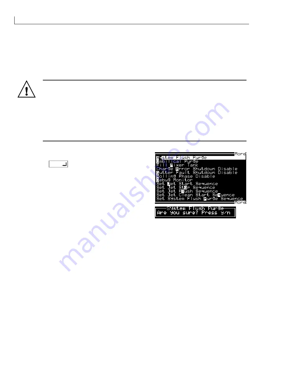
From the 

System

 menu, select 

System Flush Purge

.

Press 

enter

.

Press 

Y

 to confirm or 

N

 to cancel the operation.

The machine starts and the flush pump is actuated. During the actuation of the flush pump, solvent is ejected
from beneath the jet valve.

Allow the machine to run for approximately 30 seconds before switching off the mains electrical supply

to the machine to stop the flushing sequence.

Tighten the jet valve (V11) screws and dry the printhead.

Switch on the mains electrical supply to the machine and perform a clean start and clean stop.

Evaluate the clean start/clean stop performance. Repeat the procedure if necessary.

Содержание 430

Страница 1: ...430 Ink Jet Printer Service Manual THE WORLD S CODING AND LABELLING COMPANY ...

Страница 2: ...on for Use 4 Passwords 9 Setting up Shifts 9 Production Line Setup 10 Typical Installation 10 Throw Distance 11 Shaft Encoder 11 Internal Source 11 External Source 11 Product Sensors 13 CONSUMABLES 15 Ink and Solvent Storage 15 FIRMWARE DOWNLOAD 17 Introduction 17 Requirements 17 Windows 3 xx Procedure 17 Checking the Communications Link 17 Windows 95 98 Procedure 18 Checking the Communications Li...

Страница 3: ...e Value Calibration 37 Setting EHT Tables for Printing 38 Clean Shutdown Check 38 Set EHT Trip Level Normal Operation 39 EHT Trip Test 39 Print Height Test 39 Restore Calibration Parameters 40 Enable Gutter Detect and Charge Check 40 Ink Viscosity Measurement 41 Temperature Viscosity Graphs 41 CIJ MK 390ID Black 41 CIJ MK 3903F Red 42 CIJ MK 3930F Black 42 CIJ EA 3969H Black 43 TECHNICAL DESCRIPTI...

Страница 4: ...ocated near flush pump 83 VMS Filter located inside FMS top box 83 Fluid Management System FMS 84 Viscosity Monitoring System VMS Chamber located inside the FMS top box 84 Venturi Jet Pump located inside the FMS top box 85 Pressure Transducer located on the FMS connect manifold 85 Ink System Pump located in the base of the machine 85 Flush Pump located close to the FMS 85 Printhead Operation 86 In...

Страница 5: ...tion 117 Exchanging the Sensor and LED 117 Mains Inlet Connector 119 Removal 119 Installation 120 Mains Switch 120 Removal 120 Installation 120 Fluid Management System FMS 121 Removal 121 Installation 122 Ink System Pump 123 Removal 123 Installation 124 Main Filter 125 Removal 125 Installation 125 Flush Pump 126 Removal 126 Installation 126 Solenoid Valves 127 Removal 127 Installation 127 Fan 128 ...

Страница 6: ...Restrictor Cleaning 158 VMS Outlet Cleaning 159 Umbilical Purge 160 Printhead Alignment 161 ILLUSTRATED PARTS LIST 165 How to Use This Parts List 165 Optional Parts and Accessories 165 430 Ink Jet Printer 166 Stand and Traffic Light System 167 Options and Accessories 168 General Spare Parts and Tools 169 Documentation 169 Major Sub Assemblies 170 Top Moulding Ink System Components 171 Top Moulding...

Страница 7: ...430 Ink Jet Printer Service and Maintenance Manual vi Issue 2 Part No 306 0430 102 ...

Страница 8: ...as left right front rear clockwise and anticlockwise are given with respect to the printer when viewed from the front Units of Measurement This handbook uses SI units of measurement and their imperial equivalents Typography The names of menu options are presented in bold typeface Cross references are presented on bold italic typeface Applicable Standards Willett Limited is a BS5750 ISO9000 approve...

Страница 9: ...e ratings differ do not use the printer until you have consulted your local supplier Use only the mains power cable supplied with the printer This cable must terminate in an approved three pole mains plug which has a protective ground conductor Keep electrical power cables sockets and plugs clean and dry at all times Grounding The equipment must be connected only to an a c power supply which has a...

Страница 10: ...r notice The reader should in all cases consult the manufacturer to determine whether any such changes have been made Copyright Willett Limited 2001 Printed in the UK March 2001 Acknowledgements The Willett name and Willett logo are trademarks of Willett Limited Associated Publications Willett 430 Ink Jet Printer Instructions for Use Part Number 306 0430 101 Contact Information Willett Limited Cro...

Страница 11: ... UNDER CERTAIN OPERATING CONDITIONS THERE COULD BE SOLVENT EMISSIONS FROM THIS MACHINE ENSURE THAT THE MACHINE IS OPERATED IN A WELL VENTILATED AREA AND IF NECESSARY MONITOR CONCENTRATIONS INTHE IMMEDIATE VICINITY W A R N I N G OPERATING VOLTAGE TENSION SECTEUR BETRIEBSSPANNUNG FREQUENCY FREQUENCE FREQUENZ CURRENT COURANT ASSIGNÉ NENNSTROM POWER CONSOMMATION NENNLEISTUNG FUSES FUSIBLES SICHERUNG 1...

Страница 12: ...he preliminary pages and at their points of application in the manual They are presented in the typographical style of this notice Warning Notices WARNING LETHAL VOLTAGES Lethal voltages are present within this equipment when it is connected to the mains electrical supply Only trained and authorised personnel may carry out maintenance work Observe all statutory electrical safety codes and practice...

Страница 13: ...rect the ink stream into a beaker or suitable container To avoid contamination of the ink supply in the printer do not re use any ink collected in this way Dispose of all waste ink in accordance with local regulations WARNING VAPOUR HAZARD Prolonged breathing of top up or cleaning fluid vapour may cause drowsiness and or effects similar to alcoholic intoxication Use only in open well ventilated ar...

Страница 14: ...bes are correctly located in the ink top up reservoir before continuing otherwise there is a risk of ink spillage WARNING HANDLING INK SOLVENT AND TOP UP A high ac voltage is present at the inverter and backlight Extreme caution is required when diagnosing failure in these areas Caution Notices Caution Equipment Damage Only Willett trained personnel my carry out installation and maintenance work A...

Страница 15: ...40 Caution Equipment Damage Never attempt to bend the gutter Its position is fixed Caution Damage to Charge Electrode Take care not to deform the charge electrode slot when rotating the charge electrode Caution Charge Cable Ensure that the charge cable is not pulled out of its position in the rear face of the deflector block assembly Caution Equipment Damage Never attempt to bend the gutter It is ...

Страница 16: ...leaning agent is compatible with the ink used before carrying out printhead cleaning otherwise the printhead may be damaged Caution Equipment Damage The printhead must be completely dry before attempting to start the printer otherwise the printhead may be damaged Caution Printer Overheating Report all overheating incidents to a maintenance engineer Caution Risk of Data Loss Ensure the correct mess...

Страница 17: ...430 Ink Jet Printer Service and Maintenance Manual xvi Issue 2 Part No 306 0430 102 ...

Страница 18: ...ation criteria are met before attempting installation The site survey form must be completed as fully as possible by the sales engineer Missing or ambiguous information should be clarified by telephone or fax prior to the installation procedure WARNING LETHAL VOLTAGES Lethal voltages are present within this equipment when it is connected to the mains electrical supply Only trained and authorised p...

Страница 19: ...rinter 1 Open the top flaps of the carton and gently pull the complete machine and inserts 1 and 2 upwards from the carton 2 Place the printer and inserts on a clean level surface 3 Remove the printhead 5 from the left hand insert 1 4 Remove the umbilical 4 from its transit routeing 5 Remove the left hand insert and right hand insert 2 6 Place the printer on a clean level surface for commissioning...

Страница 20: ... the extender legs slot into their respective locating holes 4 Turn the six side cover fasteners 4 one quarter turn counter clockwise These fasteners are captive in their respective side covers 3 Caution Equipment Damage Take care not to damage the printer base internal components or wiring when removing or refitting the side covers 5 Remove the side covers noting their orientation for refitting 1...

Страница 21: ... 3 Filler Tubes Figure 3 Ink Mixer Bowl Filler Plug Location 1 Remove and retain the black rubber shipping cap from the breather tube 2 Fit the breather tube to the blue fitting located on the underside of the top cover 3 Ensure that the correct fuses Figure 4 2 are fitted for the local mains electrical supply as shown in the table below ...

Страница 22: ...assword 8 Remove the filler plug Figure 3 1 and prime the mixer bowl 2 with approximately 250 ml of the correct ink using a syringe and a length of 40 mm x 6 mm tube The Ink Out icon will cease to be displayed when approximately 250 ml is added to the mixer bowl WARNING HANDLING INK SOLVENT AND TOP UP The ink solvent and top up are irritating to the eyes and respiratory system To prevent personal ...

Страница 23: ...nd plug for refitting if the machine has to be transported 17 Mount the printhead to a suitable support 18 Disable Gutter Detect as follows a Access the System menu b Select Gutter Fault Shutdown Disable c In the Machine Control sub menu set Gutter Fault to Disable and press enter 19 Disable Charge Check as follows a Access the System menu b Select Charge Error Shutdown Disable c In the Machine Co...

Страница 24: ...t Temperature 35 Ambient temperature Viscosity Set Point 29 Ink type Ambient temperature Phase Angle Any value must be stable Correct Jet Break up Ink Temperature 25 Ambient temperature Head Temperature 25 35 Ink type heater set point Viscosity Actual 29 Indicated value 1 compared to Viscosity Set Point correct viscosity Phase Profile 08 09 Ideal Phase charge charge value Phase pick up position In...

Страница 25: ...fety glasses when carrying out maintenance Apply barrier hand cream before handling ink If cleaning agent contaminates the skin rinse off with running water for at least 15 minutes d From the System menu select System Flush Purge e Press enter f Press Y to confirm or N to cancel the operation The machine starts and the flush pump is actuated During the actuation of the flush pump solvent is ejecte...

Страница 26: ... if any The example below show how to set a shift system where the day is split into three shifts with each shift numbered from 1 and shift 1 starting at 0700 1 From the Configure menu select Set Shifts The Set Shifts sub menu is displayed 2 Set the shift parameters as follows Start hour of shift 1 7 Start minutes of shift 1 00 Character for shift 1 1 Shift length hours 8 Shift length minutes 00 N...

Страница 27: ... printer 7 is mounted on a printer stand 6 The printhead 4 is configured to print vertically via a clamp 2 and bracket 3 assembly A lamp stack 1 is fitted to the printer stand 1 Lamp stack 2 Clamp 3 Bracket 4 Printhead 5 Photocell cable 6 Printer stand 7 Printer 8 Photocell 9 Shaft encoder cable 1 2 3 4 5 7 9 10 6 8 10 Shaft encoder Figure 6 Typical Production Line Installation ...

Страница 28: ...e Configure menu Figure 6 shows an external shaft encoder 10 connected via a cable 9 to the SHAFT ENCODER connector on the connector panel The printer can be configured to accept two shaft encoder quadrature outputs This allows the printer to compensate for changes in direction of the production line Caution Electrostatic Sensitive Devices The printed circuit boards contain static sensitive device...

Страница 29: ...ntenance Manual 12 Issue 2 Part No 306 0430 102 1 3 2 3 2 1 Input Output board 2 Sensor 2 Quadrature shaft encoder jumper JB2 3 Print trigger 1 and 2 jumper JB1 Figure 7 Input Output Board Product Sensor and Shaft Encoder Jumper Location ...

Страница 30: ...s may be either NPN or PNP devices Set Jumper JB1 Figure 7 3 on the I O board to match the device type Table 1 lists the settings for jumper JB1 Table 1 Jumper JB1 Settings Print trigger Device type Jumper 1 Pins Jumper 2 Pins 1 NPN A 1 2 C 3 4 1 PNP B 2 3 D 4 5 2 NPN F 6 7 H 8 9 2 PNP G 7 8 I 9 10 2 Connect the printer to the mains supply and set the on off switch to I on 3 Select the Photocell S...

Страница 31: ...430 Ink Jet Printer Service and Maintenance Manual 14 Issue 2 Part No 306 0430 102 ...

Страница 32: ... fire risk as they will not burn or support combustion Inks based on water alcohol mixtures may burn if sufficient alcohol is present Solvent based inks pose a greater fire risk Consult the appropriate product data sheet on the exact nature of the ink solvent Use powder or dry foam to extinguish fires and ensure electrical supply is turned off A fire blanket may be used to smother small local fire...

Страница 33: ...hat become saturated with these substances Dispose of all such items in accordance with local regulations In the event that any ink solvent or top up container is not completely empty after use it should be resealed Only full bottles are recommended for use when replenishing ink or top ups partially filled bottles should be disposed of in accordance with local regulations WARNING VAPOUR HAZARD Pro...

Страница 34: ...ws 95 or Windows 98 A copy of the new operating software on disk A suitable serial communications cable to connect between the PC and printer connector COMM1 see Section 5 for connection details Windows 3 xx Procedure Checking the Communications Link Before attempting to download new software check the communications link between the PC and the printer 1 Using a pre configured connection cable con...

Страница 35: ... e g MON MON 12 Press X and then enter on the PC to return the printer to normal control 13 From the Data Logging menu select the Serial Port Functionality option 14 Reset Status to Enable Windows 95 98 Procedure Checking the Communications Link 1 Before attempting to download new software check the communications link between the PC and the printer 2 Using a pre configured connection cable connec...

Страница 36: ... the port to be used 7 Click OK to confirm the settings 8 If required this set up can be saved for future use by selecting Save As from the File menu and saving the communications set up as for example 430 trm 9 Ensure that port COMM1 on the printer is set to corresponding baud rate data bits stop bits and parity settings 10 From the Data Logging menu select the Serial Port Functionality option an...

Страница 37: ... Monitor 3 Select LCD and press enter The printer screen displays MON 4 On the PC double click on Terminal normally located in Accessories group Figure 10 Windows 3 xx Accessories Group 5 Type BO on the printer keypad and press enter 6 Press the Y key to confirm The screen display becomes blank and the Terminal Window displays MON 7 On the PC type ER and press enter to erase the printer flash EEPR...

Страница 38: ...COMM1 2 Select the System menu 3 Select LCD and press enter The printer screen displays MON 4 Access Windows HyperTerminal normally located by clicking Start Programs Accessories Communications HyperTerminal 5 Follow the instructions for establishing a connection see Preparation for Use page 4 6 Type BO on the printer keypad and press enter 7 Press the Y key to confirm The screen display becomes b...

Страница 39: ...ays MON 16 At the terminal MON prompt type SET 4000 3ffff 0 and press 17 At the terminal MON prompt type SET 1000 37ff 0 and press 18 At the terminal MON prompt type SET 200 400 0 and press 19 Type RUN on the PC keyboard and press enter to activate and run the new operating software 20 Carry out a full system reset see Configure Menu page 105 ...

Страница 40: ...m may lock up If this situation occurs use the following recovery procedure 1 Switch off the 400 Series unit 2 Remove the I O board to allow access to the CPU 3 Connect test point TMR1 to the chassis 0 V with a test lead TMR1 is the test point closest to R12 1 CPU board 2 Test lead 1 3 2 3 Pillar 0 V Figure 11 Connection of TMR1 to chassis 4 Replace the I O board and connections 5 Connect a PC to ...

Страница 41: ... 0430 102 7 Run the PC in Windows Terminal Mode and establish communication 8 At the PC type ER 9 Switch off the printer and remove the test lead from the CPU 10 Switch on the printer and download new software using the download procedure The printer will now be operational ...

Страница 42: ...EARTH CONTINUITY To ensure safe earthing the resistance between the mains lead earth wire and the test points must be less than 1 Ω 1 Using the multimeter test between the green yellow earth wire in the mains lead and the following points 2 The front and rear panels 3 With the covers removed from the printer and the top moulding raised check between the green yellow wire in the mains lead and the ...

Страница 43: ... Out icon is displayed Pump Zero Offset Calibration Caution False Readings To avoid the risk of false readings the pump zero offset should only be calibrated when there is no ink in the system and the pump is off Calibrate the pump zero offset as follows 1 From the Calibrate menu select the Pump Zero Offset option 2 Press enter 3 Press Y to confirm or N to cancel the operation The ink system press...

Страница 44: ... green 12 V customer s isolated supply for shaft encoder photocell LED2 clear lens that glows red when illuminated 285 V 15 V dim with printhead cover off 285 V bright with printhead cover on LED3 yellow 24 V supply LED4 red 15 V supply LED5 green 24 V valve pump heater supply 2 Refit the cabinet side covers when the checks are complete 1 3 2 4 5 1 LED 4 red 15 V 3 LED 2 red 285 V 5 LED 1 green 10...

Страница 45: ...ut this check PIN 8 24 V PIN 7 0 V PIN 6 24 V PIN 5 5 V PIN 4 15 V PIN 3 5 V PIN 2 0 V PIN 1 15 V Figure 14 I O board POWER connector Reset Run Hours If the Service icon is displayed the time until the next service is due must be entered to remove it Proceed as follows 1 From the Data Logging menu select Reset Run Hours 2 Press enter 3 Select Set pump alarm hours Enter the number of hours until th...

Страница 46: ...fore setting the EHT range and trip level The preliminary settings ensure that EHT trip is prevented when setting up the printhead and calibrating the EHT table 1 Fit the printhead cover 2 From the Calibrate menu select EHT Range Set 3 Press enter 4 Select EHT Value 1 and set the value to 255 5 Select EHT Value 10 and set the value to 255 6 Press enter to save the settings Set EHT Trip Level for p...

Страница 47: ...eter plastic tube Note The Ink Out icon will clear from the display before all the ink is added to the mixer tank but ensure that the entire 250 ml of ink is added Caution Equipment Damage Ensure that the ink comes from a sealed bottle and that at least one of the bottles from the same batch has been tested to ensure that the viscosity is correct Note A list of part numbers for ink and top up and ...

Страница 48: ...op up being used with the machine press esc 4 Select Ink Number from the Calibrate menu and press enter 5 Press the or key to scroll to the correct Ink Part No for the Fluid ID No 6 Press the key to highlight the Top up Part No 7 Press the or key to scroll to the correct Top up Part No for the Fluid ID No and press enter Note A list of part numbers for ink and top up and FINs appears in Illustrate...

Страница 49: ...sting VR1 on the I O board Disconnect the multimeter 5 Seal VR1 adjustment screw using a suitable sealing compound Refit the electrical connectors to valves V6 and V1 VMS Calibration Caution Equipment Damage Ensure that the ink comes from a sealed bottle and that at least one of the bottles from the same batch has been tested to ensure that the viscosity is correct 1 Remove the solvent addition ac...

Страница 50: ...onal for 2 minutes but can be aborted at any time by pressing f1 Abort Flush Strobe LED Check Check that the red strobe LED situated behind the charge electrode is illuminated Ink Jet Alignment 1 Press f1 to start the jet 2 Ensure that the jet is in the correct position with the charge electrode see Figure 15 and is passing through the centre of the charge electrode slot with an equidistant gap 1 ...

Страница 51: ...nd should have been set automatically when the FIN was entered in the Fluid Identification Number FIN page 31 The Head temperature is typically 35 but can vary for some inks Ensure that the temperature set point is correct for the ink being used refer to the last 2 digits of the FIN Ink pressure is typically 32 but can vary for some inks Ensure that the pressure set point is correct for the ink be...

Страница 52: ...tion Set Level 5 Press enter 6 View the position of the jet break off Adjust the Modulation Set Value until the modulation level is 5 7 Observe the jet in the viewing area illuminated by the strobe LED 8 Whilst observing the jet slowly increase the modulation until the satellites start to merge with the main drops 9 Continue to increase the modulation until all the satellites have just merged and ...

Страница 53: ...T LIGAMENT VERY LOW HIGH VERY HIGH CHARGE ELECTRODE CHARGE ELECTRODE SATELLITE SATELLITE Figure 16 Inkjet Break off Point 12 When a good break off point is achieved press enter Enable the Rolling Phase 13 From the System menu select Rolling Phase Disable and press enter 14 Toggle to Enable then press enter ...

Страница 54: ... screen and press alt L C b The display shows Phase Charge c Press or to adjust the Phase Charge until the correct Phase profile is displayed then press enter d Press esc to exit the Diagnostics screen 5 Ensure that the jet is 4 mm 0 25 mm from the ve EHT plate Also ensure that the 0 V EHT plate is parallel to the jet If any adjustments are required refer to the printhead alignment procedure in Pr...

Страница 55: ...after inputting each value and take print samples until the minimum readable character is achieved gutter clipping Set this value Note If gutter clipping occurs clean the gutter before proceeding 7 Set the Character Height for the currently selected message to 10 8 Set EHT Value 10 to 200 Increase the value in steps of 10 and take print samples until the maximum readable character is achieved Note...

Страница 56: ...ter height to 10 then press enter 7 To prevent the machine from shutting down set the charge gutter detect to DISABLE as instructed in Gutter Fault and Charge Error Disable page 29 8 Fit the modified EHT printhead cover and press f1 to start the Jet 9 Insert the EHT Trip Tool between the ve deflection plate and the 0V plate The point of the tool should be towards the ve plate lower 10 Ensure that ...

Страница 57: ...librated parameters 1 From the Configure menu select Restore System Settings 2 Press enter to restore the settings Enable Gutter Detect and Charge Check 1 From the System menu select Charge Error Shutdown 2 Press enter 3 Select Charge error and toggle to Enable 4 Select Gutter fault and toggle to Enable 5 Press enter to enable both functions ...

Страница 58: ...on the thermometer 6 Apply the temperature compensation factor given on the graph supplied with the viscometer to the time recorded and trace a reading on the main Time versus Viscosity graph supplied with the viscometer Caution Incorrect Measurement If the temperature compensation factor is not used the end result could be incorrect by as much as 40 7 Refer to the temperature versus viscosity gra...

Страница 59: ...430 Ink Jet Printer Service and Maintenance Manual 42 Issue 2 Part No 306 0430 102 CIJ MK 3903F Red CIJ MK 3930F Black 3 4 5 6 7 8 5 10 15 20 25 30 35 40 Temperature deg C Viscosity CPS ...

Страница 60: ...System Calibration and Test Ink Viscosity Measurement Issue 2 43 Part No 306 0430 102 CIJ EA 3969H Black 3 4 5 6 7 5 10 15 20 25 30 35 40 Temperature deg C Viscosity CPS ...

Страница 61: ...430 Ink Jet Printer Service and Maintenance Manual 44 Issue 2 Part No 306 0430 102 ...

Страница 62: ...I O Connector PEC1 Table 12 I O Connector PEC2 Table 13 I O Connector SENC Table 14 I O Connector LEDS Table 15 I O Connector T LIGHT Table 16 I O Connector LEVELS Table 17 I O Connector CON_B1 Table 18 I O Connector CON_EX Table 19 I O Connector PIGS Table 20 I O Connector VALVES Table 21 I O Connector CON_BM2 Table 22 I O Connector CON_BM2 Table 23 I O Connector P TRANS Table 24 I O Connector HE...

Страница 63: ...el 8 Filter cover 9 Side cover 10 Base 1 2 4 5 6 7 9 6 3 8 9 10 11 4 11 Umbilical outlet Figure 17 Printer Cabinet Top Cover The top cover 5 is moulded from a plastic material and houses the following The control panel 3 A hinged reservoir filler cover 1 that gives access to the ink and top up reservoir fillers A vent 2 that allows heat and vapour to escape from the enclosure The top cover is secu...

Страница 64: ...ed using quick release fasteners 6 which have combined slotted pozi heads to facilitate removal When the covers are removed the fasteners are retained in the cover by captive plastic washers Base The base 10 is moulded from plastic and houses the following The ink system filters see Ink System Filters page 82 and the electronic system cooling fan filter A hinged cover 8 which gives access to the i...

Страница 65: ...18 1 Ground potential deflector electrode 7 Rear cover 13 LED 2 Phase detector 8 Head manifold 14 High voltage deflector electrode 3 Charge electrode 9 Umbilical 15 Gutter 4 Nozzle assembly 10 Gutter detect 16 Front cover 5 Cover switch 11 Ceramic transducer 17 Jet valve 6 Knurled screw 12 Nozzle jet orifice 18 Bleed valve Figure 18 Printhead ...

Страница 66: ...und potential deflector electrode 1 and the high voltage deflector electrode 14 are parallel rectangular plates The deflector electrodes generate a constant electrostatic field through which the electrically charged ink droplets pass The charged ink droplets are deflected by the electrodes the amount of deflection is dependent on the charge applied to the ink droplet The gutter 15 is the return pa...

Страница 67: ...430 Ink Jet Printer Service and Maintenance Manual 50 Issue 2 Part No 306 0430 102 Figure 19 Printhead Electrics and Ink System Wiring Diagram ...

Страница 68: ...S D F G H J K L Z X C V B N M backspace enter shift _ del caps ctrl shift alt i fn enter f4 1 2 3 4 5 Figure 20 Control Panel The control panel consists of the following A 70 key industrial grade membrane keypad 2 The keypad is self adhesive for ease of mounting and is fixed to an aluminium plate which is secured to the top cover by six screws A 240 x 128 pixel backlit Liquid Crystal Display LCD 1...

Страница 69: ...ter set s selected for the keypad The arrow keys 4 to the right of the display allow you to navigate through the software menu system The light emitting diodes LEDs 5 on the top right of the display indicate the system status as follows LAMP S ILLUMINATED SYSTEM STATUS RED Any fault that prevents printing e g jet not running EHT trip AMBER and GREEN The printer requires user intervention to preven...

Страница 70: ...is a stainless steel pre drilled plate fitted to the printer base and secured by four screws The connector panel is fitted with the components listed below A mains inlet connector 3 with a single pole rocker switch 1 and fuseholders 2 for supply and return lines A 3 way DIN connector 4 for print trigger 1 A 4 way DIN connector 5 for a shaft encoder A 5 way DIN connector 6 for an RS232 serial commu...

Страница 71: ...haft encoder output A DIN Pin 3 Shaft encoder output B Din Pin 4 0V DC common Note The shaft encoder output must of the PUSH PULL type COMM 1 Connector The printer has an RS232 communication port linked to the COMM1 connector Figure 21 6 the pin allocation is as follows Pin Function DIN Pin 1 0VDC common DIN Pin 2 Transmit data out from the printer DIN Pin 3 Received data into the printer Din Pin ...

Страница 72: ... the 400 series printer to operate as designed it has three other electronic component parts These are the modular power supply PSU 1 the Liquid Crystal Display LCD and the integral keypad The PSU connects directly to the I O board but the LCD and KEYPAD connect directly to the CPU Note that the LCD backlight inverter connects to the I O board The printer can be interrogated over a serial link in ...

Страница 73: ...Issue 2 Part No 306 0430 102 CPU Board The CPU Board circuit diagram is included Appendix A in this manual 1 CPU board 2 IC U31 3 IC U40 and U41 4 IC U38 and U39 5 IC U19 6 Ni MH battery 7 IC U21 1 2 3 4 5 6 7 8 8 IC U9 Figure 23 CPU Board Major Components ...

Страница 74: ...om Access Memory RAM devices that contain the printer configuration calibration and message storage memory To avoid loss of data when the printer is switched off they are backed up by a Nickel Metal Hydride Ni MH battery IC U19 5 is the microprocessor that monitors incoming data from the I O ports and translates software commands into machine statements that control the electronic system and ink s...

Страница 75: ...nnectors The CPU board connectors shown in Figure 24 Pinout details are given in the tables below 1 2 3 4 5 6 7 9 8 1 CON_K 4 CON_S 7 CON_L 2 CON_232 5 CON_P Interboard connector 8 Link W3 3 CON_B Interboard connector 6 CON_D Interboard connector 9 CON_LAN Figure 24 CPU Board Connectors ...

Страница 76: ...o Signal Function Pin No Signal Function 1 TXDA Transmit data 4 DCD Data carrier detect 2 DTR Data terminal ready 5 COM Common 3 RXDA Receive data 6 8V Table 4CPU CON_232 RS232 Serial Interface CON_B 3 is an interboard connector which connects the CPU board to the I O board Pin No Signal Function Pin No Signal Function 1 0 V Common 11 opto I O Expansion board enable 2 Sel2 Not used 12 adc A D conv...

Страница 77: ...in out from PSU via I O 11 and 12 15 V 15 V input from PSU via I O 5 to 8 5 V 5 V input from PSU via I O 13 and 14 GND via I O 9 and 10 15 V 15 V input from PSU via I O Table 7CPU CON_P Power Input Connector CON_D 6 is an interboard connector which connects the CPU board to the I O board Pin No Signal Function 1 to 8 00 07 Droplet charge data 9 and 10 0 V Common 11 to 20 Not used at present Table ...

Страница 78: ...unction 1 15 V 15 VDC power 5 DTR Data terminal ready 2 VCC 5 VDC power 6 0 V Common 3 RXDB Receive data 7 RXDB Receive data via inverter 4 TXDB Transmit data 8 TXDB Transmit data via inverter Notes Pins 7 and 8 of the CPU CON_LAN serial port are for use with a modem Link W3 8 must be fitted if COM2 is to be used with the optional expansion card and internal modem Link W3 must be removed if COM2 i...

Страница 79: ...3 I O board Major Components 1 I O board 2 IC U20 3 Ink Pump motor driver board 4 IC U1 5 VR1 6 285 V DC power supply 7 IC U15 J1 401 0193 101 ISS 1 VALVES I O VALVES D2 R23 R24 V3 R26 R10 R19 R27 C13 C12 R48 R37 R35 R16 R3 R38 R6 R14 J2 R1 CON 1 CON 2 R43 R45 R4 R44 R39 R52 R54 R55 R49 R50 R33 V5 C15 C14 R51 D10 D8 R53 D11 D9 C8 R28 JP1 V1 C1 C7 C9 R29 JP2 R31 R12 R13 R32 R7 R25 R11 R17 R20 R30 C...

Страница 80: ...ON_BM1 and CON_BM2 IC U1 4 acts as the ink pump motor controller A circuit diagram of the board is supplied in Appendix A in this manual The 300 VDC power supply 6 provides the voltage supply to the charge amplifier which is used to charge the ink droplets IC U15 7 is a Programmable Peripheral Interface PPI which is used to read the states of various sensors and control functions and to switch con...

Страница 81: ...6 8 7 9 10 11 12 13 14 15 16 17 18 19 20 21 22 23 24 1 PEC1 6 LEVELS 11 CON_BM2 16 HEAD_1 21 FAN_FAIL 2 PEC2 7 CON_B1 12 PUMP 17 CON_P0 22 CON_D 3 SENC 8 CON_EX 13 P TRANS 18 POWER 23 B LIGHT 4 LEDS 9 PIGS 14 HEAD_2 19 CH MOD 24 JB1 5 T LIGHT 10 VALVES 15 CON_BM1 20 EHT FAN Figure 26 I O Board Connectors ...

Страница 82: ...in No Signal Function 1 V0 Positive DC supply to shaft encoder 2 SHAFT ENCODER A Input A from shaft encoder 3 SHAFT ENCODER B Input B from shaft encoder 4 0 V Common Table 13 I O Connector SENC LEDS 4 LEDs are fitted on the front panel to mimic traffic lights Pin No Signal Function Pin No Signal Function 1 Red Red LED anode 5 Red Red LED cathode 2 Yellow Yellow LED anode 6 Yellow Yellow LED cathod...

Страница 83: ...ev1 Mixer low sensor output 21 5 V 5 V Ink res low sensor LED anode 5 5 V 5 V Mixer OK sensor LED anode 22 5 V 5 V Ink res low sensor phototransistor collector 6 5 V 5 V Mixer OK sensor phototransistor collector 23 0 V 0 V Ink res low sensor LED cathode 7 0 V 0 V Mixer OK sensor LED cathode 24 lev6 Ink res low sensor output 8 lev 2 Mixer OK sensor output 25 5 V 5 V Solvent res low sensor LED anode...

Страница 84: ... pec2 Photocell 2 shaft encoder quadrature output 31 pcs3 PPI enable 8 print pha se Print phase 32 shaft enc Shaft encoder output 9 strobe LED strobe 33 extra 1 Traffic light enable 10 pwm Pump control pulse width modulation 34 contrast LCD contrast Table 17 I O Connector CON_B1 CON_EX 8 Interboard connector to I O board to the optional expansion board Pin No Signal Function Pin No Signal Function...

Страница 85: ... up valve control signal 12 ve Gutter valve control signal 5 24 V 24 V DC to VMS diverter valve V3 13 24 V 24 V DC auto power off 6 ve VMS diverter valve control signal 14 ve Auto power off control signal 7 24 V 24 V DC to solvent flush valve V4 15 24 V 24 V DC to purge valve V10 8 ve Solvent flush valve control signal 16 ve Purge valve control signal Table 20 I O Connector VALVES CON_BM2 11 Ink p...

Страница 86: ...ucer Pin No Signal Function Pin No Signal Function 1 10 V 10 V DC supply voltage to transducer 5 BULK INK TEMPER ATURE Output from mixer tank temperature sensor 2 ve ve output from transducer 6 0 V 0 V to temperature sensor 3 ve ve output from transducer 7 5 V 5 V DC to temperature sensor 4 0 V 0 V to transducer 8 GND Table 23 I O Connector P TRANS HEAD_2 14 Printhead connector 2 via the umbilical...

Страница 87: ...ase detector amplifier 6 0 V 0 V connection to LED cathodes 2 12 V 12 V DC to phase detector amplifier 7 STROBE LED Strobe signal to LED anode 3 0 V 0 V connection to phase detector amplifier 8 Signal from phase detector amp 4 GUTTER DETECT Oscillator signal to gutter detect 9 LID SWITCH ve to lid switch 5 0 V 0 V connection to gutter detect 10 0 V 0 V connection to lid switch Table 26 I O Connect...

Страница 88: ...ulation 0 V 2 0 V CHARGE Charge amplifier 0 V 4 mod 1b Modulation signal output Table 29 I O Connector CH MOD EHT FAN 20 Cooling fan and EHT module Pin No Signal Function Pin No Signal Function 1 0 V 0 V 6 EHT ve supply to EHT module 2 24 V SW 24 V DC switched 7 EHT ve supply to EHT module 3 PUMP 24 V DC 8 VCC 5 V DC 4 24 V SW 24 V DC switched fan 9 Lev 8 Spare digital input 5 FAN ve fan supply 10...

Страница 89: ...EC2 PEC1 is connected to product error 1 via the connector panel PEC2 is connected to product error 2 via the connector panel Table 34 I O Board Jumper Test point Signal LED Colour Function TP1 14 0 V LED1 11 green Customer 10 V isolated supply present TP2 8 285 V DC charge amplifier supply LED2 9 red Charge amplifier supply TP3 12 Ink temperature at viscometer delivery line LED3 6 yellow 24 V TP4...

Страница 90: ...n Control Electronics Issue 2 73 Part No 306 0430 102 1 TP9 2 TP7 3 TP6 4 TP8 5 LED4 6 LED3 7 TP4 8 TP2 9 LED2 10 LED5 11 LED1 12 TP3 13 TP5 1 2 4 5 6 3 10 11 12 14 13 9 8 7 14 TP1 Figure 27 I O Board Test Points and LEDs ...

Страница 91: ...it diagram is included Appendix A in this manual The Ink Pump Motor Driver Board is a separate plug in PCB which is based on the Motorola MC33033 controller It contains the controller logic and drive circuits to control the three phase brushless motor with Hall effect position sensors which are used to drive the pump The speed of the motor is determined by the Pulse Width Modulation PWM input from...

Страница 92: ...rd set up Also included on this board is a circuit to oscillate the gutter valve on and off at a pre selectable frequency of 3 Hz or 6 Hz Selectable by J4 which can also disable the circuit The effect of this circuit is to reduce the solvent consumption caused by sucking back excess air This valve oscillation only occurs when the machine is printing or is ready to print i e EHT is on therefore it ...

Страница 93: ...turned on and the drain remains close to the CONTROL rail thus the valve has 24 V across it As R53 charges C14 after approximately 50 ms the gate source voltage drops to a point where the FET turns off effectively leaving the valve in series with R54 As this is 280 ohms and the valve is 280 ohms there is a potential of 12 V across the valve When the software turns the valve off the CONTROL line is...

Страница 94: ...ication Output Specification Load A Output Voltage V Min Rated Max Tolerance Ripple Noise mV Line Reg _ Load Reg 5 0 5 4 8 1 50 1 1 15 0 0 5 1 10 100 2 8 15 0 0 5 1 10 100 2 8 24 V 0 1 2 2 5 5 150 1 5 Table 37 PSU Board Output Specifications Notes Each output can provide up to a maximum load but total load cannot exceed 85 W continuously 5 V output is adjusted to 1 at 60 rated load at factory Tole...

Страница 95: ... compartment cooling fan 3 blows filtered air over the electronics system to cool it The fan is also used to dilute and disperse vapour produced from the ink system A fan failure card 2 monitors the flow of cooling air in the filter compartment if the fan fails then the flow of cooling air stops this is detected by the fan failure card which outputs an alarm signal to the CPU via the I O board Ink...

Страница 96: ... connector the live and neutral lines are fed to the On Off switch via a filter the earth line is connected directly to an earth lug on the PSU The output from the On Off switch is fed to connector TB1 on the PSU via fuses 1 and 2 Fuse ratings are 3 15 A for a 220 240 V supply and 5 A for a 110 V supply N L TB1 PSU F1 F2 N L E Figure 31 Mains Input Circuit The live and neutral lines are protected ...

Страница 97: ...ected by PTFE tubing Figure 32 shows the ink system components 1 16 15 14 13 2 3 4 5 6 7 11 12 8 9 10 1 Ink reservoir manifold 7 FMS 13 Top up reservoir 2 Top up reservoir manifold 8 Pressure transducer housing 14 Ink reservoir 3 Solenoid valve V6 Ink 9 Mixer tank 15 Ink system pump 4 Solenoid valve V8 Gutter 10 Flush pump 16 Solenoid valve V1 Top Up Addition valve 5 Solenoid valve V3 VMS 11 Pre p...

Страница 98: ...e FMS mixer tank falls below the Mixer tank OK ink level detector V3 VMS Diverter Valve located on the FMS ink system The VMS diverter valve 5 controls the flow of ink into the VMS chamber via restrictor R1 which controls the ink viscosity V3 is energised when the VMS system becomes operational under software control or when the ink level falls below the VMS low level detect probe V3 is de energis...

Страница 99: ...ed in the printhead V12 when energised allows ink to flow through the nozzle return pipe V12 is energised during printhead umbilical purging and momentarily during jet start up and shutdown 1 Normally open port R 2 Normally closed port P 1 2 3 3 Common port C Figure 33 Solenoid Valve Top Up and Ink Reservoirs The ink and top up reservoirs Figure 32 14 13 are of similar design and each have a capac...

Страница 100: ...lly be introduced into the system pipe work The pre head filter is fitted to trap these particulates The filter medium is stainless steel with a filtration rating of 8 microns Nozzle Filter located behind the nozzle in the printhead The nozzle filter which is fitted to the clean nozzle assembly during manufacture is a last chance filter designed to prevent ingress of particulates into the nozzle w...

Страница 101: ...w sensor 5 Mixer tank ink temperature sensor 8 Viscosity Monitoring System VMS 1 Viscosity Monitoring System VMS Chamber located inside the FMS top box The VMS chamber is small and incorporated as part of the FMS ink system top box moulding The top of the VMS chamber is covered by an injection moulded cover which is secured with a gasket and four screws The VMS top cover incorporates a pre formed ...

Страница 102: ...within limits a constant printing pressure Ink System Pump located in the base of the machine The ink system pump Figure 32 10 is a positive displacement gear pump driven by a 24 V dc brushless motor The pump provides stable ink pressure to the nozzle during printing and also provides a flow of ink to the VMS and Venturi jet pump for drawing unused ink from the printhead and returning it to the FM...

Страница 103: ...zzle has a damping mass 6 and 7 attached to the rear of the transducer to mechanically tune the nozzle assembly to the modulation frequency The ink droplets are produced at the same rate as the modulation frequency are uniform in size and separated by equal distances The nozzle orifice diameter is 60 microns 1 Nozzle jet orifice 2 Nozzle assembly 3 Ink feed pipe 4 Crystal transducer 5 Crystal tran...

Страница 104: ...ter passing through the charge electrode the droplet stream passes through an electrostatic field maintained by the deflector electrodes which are connected to a high tension supply typically 6 kV The negatively charged droplets are deflected by the field towards the high voltage deflector electrode Figure 37 5 The distance a drop is deflected is proportional to the charge carried which is in turn...

Страница 105: ... of ink or solvent will be rapidly mixed in Filtered ink is fed from the pump to three sub systems The VMS The printhead nozzle The venturi which applies a vacuum to the nozzle or the gutter to perform the following operations a To remove debris from the nozzle during flushing b To draw solvent through the umbilical tubes thus cleaning them during shut down c To collect non deflected ink droplets ...

Страница 106: ...ressing f1 to STOP JET This procedure is as follows 1 Solenoid valve V3 opens directing ink into the VMS chamber which is an integral part of the FMS Figure 38 GUTTER Figure 38 VMS Sequence Sheet 1 2 Ink flows into the VMS chamber via V3 and restrictor R1 until the high level sensor is covered At this point V3 closes stopping the flow of ink into the chamber Figure 39 NOZZLE FILTER GUTTER Figure 3...

Страница 107: ...hine operation as well as by its temperature which is monitored by a sensor in the mixer tank 5 The CPU compares the time taken for the ink to drain against a value calculated by the software The software takes into account the type of ink entered during system calibration and its temperature 6 If the ink is too thick i e the time to drain is longer than the calculated value solenoid valve V1 open...

Страница 108: ...o pressurise the flush pump Figure 42 5 Wait 3 seconds then jet valve V11 opens to start jet with pure flush 6 Run with pure flush for 5 seconds 7 Ink feed valve V6 opens to allow ink to nozzle Figure 43 8 Wait 4 seconds while ink and flush are jetted through nozzle 9 Bleed valve V12 opens 10 Wait 2 seconds then V7 closes 11 Wait 10 seconds to bleed nozzle 12 Bleed valve closes Figure 44 13 Wait 5...

Страница 109: ...nance Manual 92 Issue 2 Part No 306 0430 102 GUTTER Figure 42 Clean Start Jet Sequence Pressurise Flush Pump and Eject Solvent out of Nozzle NOZZLE FILTER PRE HEAD FILTER GUTTER Figure 43 Clean Start Jet Sequence Change from Solvent to Ink ...

Страница 110: ...Start Jet Sequence When the clean start jet sequence is initiated the following automatically takes place 1 Ink system pressure set to 4 bar 2 Gutter valve V8 opens 3 Wait 3 seconds ink pressure valve V6 opens 4 Wait 2 seconds jet valve V11 opens 5 Wait 2 seconds bleed valve V12 opens 6 Wait 10 seconds bleed valve closes 7 Wait 5 seconds modulation phasing and EHT switch on ...

Страница 111: ...d on 5 Wait 1 second flush valve V7 opens 6 Wait 1 second ink feed valve V6 closes Figure 46 7 Wait 5 seconds bleed valve V12 closes 8 Wait 2 seconds bleed valve opens 9 Jet feed valve V11 closes 10 Wait 500 ms gutter valve V8 and flush valve V7 closes 11 Wait 500 ms bleed valve V12 closes 12 Wait 500 ms bleed valve V12 and flush valve V7 are switched off Figure 47 13 Wait 500 ms gutter valve is s...

Страница 112: ...2 95 Part No 306 0430 102 NOZZLE FILTER PRE HEAD FILTER GUTTER Figure 46 Clean Stop Jet Sequence Stop Ink Supply and Continue with Pure Flush PRE HEAD FILTER NOZZLE FILTER GUTTER Figure 47 Clean Stop Jet Sequence Stop Ink Supply and Re fill Flush Pump ...

Страница 113: ...h off Nozzle Flush When Nozzle flush is selected the vacuum from the venturi is applied to the return side of the nozzle creating suction at the nozzle orifice Solvent is applied to the nozzle orifice to clear any blockage Figure 48 PRE HEAD FILTER NOZZLE FILTER GUTTER Figure 48 Nozzle Flush Nozzle flush will automatically time out after 2 minutes but can be stopped at any time before that by pres...

Страница 114: ...level of fluid in the mixer tank falls below the level OK sensor the ink top up valve V2 is energised Ink from the reservoir flows round the system into the mixer tank until the level OK sensor is covered V2 is then de energised Figure 49 NOZZLE FILTER PRE HEAD FILTER GUTTER Figure 49 Ink Addition to Mixer Tank ...

Страница 115: ...n the CPU memory It takes into account the type of ink in the machine entered by the operator during calibration and the ink temperature as measured by the sensor in the mixer tank If the actual time to empty is greater than the reference value the viscosity of the ink is too high Solvent top up valve V1 is energised for up to 5 seconds every 2nd VMS sequence until the viscosity is corrected Figur...

Страница 116: ...oll through the items by repeatedly pressing or Using the Keypad To select a menu or item press the combination of the alt key and the letter highlighted in the menu or item name For example press alt M to select the Messages menu alt E is useful to access the Editor menu while editing a message Entering Text Numbers and Toggle Values To enter text into a field simply type the required text or spe...

Страница 117: ...age are set to the default values Delete Message Opens the Select Message to Delete menu The selected message is deleted Copy Message Opens the Copy Message dialogue Enter a message name to copy From and a message name to copy To If the message name to copy to is an existing message an Already exists Overwrite it dialogue is opened answer with Y or N Otherwise a new message is created Message Sele...

Страница 118: ...sage Save Message Saves the message being edited and continues editing Save and Exit SHIFT F1 Saves the message being edited and exits the editor screen Clear Message Deletes the entire content of the message being edited Abandon Exits the editor screen without saving any changes to the message User Fields Menu User Fields Menu Menu Option Function Edit user field Opens the Select user field to ed...

Страница 119: ...nds a signal to an external control system normally via COMM1 Same as the Print acknowledge on the Print Control menu The Print acknowledge option can be set to Off After Comp After Prin or After both The Print ACK code option can be set between 1 and 255 Password Menu Password Menu Menu Option Function Enter Password Opens the Enter Password dialogue together with the Current password level The u...

Страница 120: ...nd a dialog opens Are you sure YES NO Umbilical Purge When using Umbilical Purge the umbilical feed and return tubes must be disconnected from the nozzle feed and return tubes Loop the umbilical feed and return tubes together and cap the nozzle feed and return tubes see Umbilical Purge maintenance procedure Opens the Umbilical Purge dialogue Select Enable to start and Disable to stop the umbilical...

Страница 121: ...ing and sequence of the valves in the ink system for the jet flush process Opens the Jet flush sequence dialogue with a warning This facility should only be used by experienced Willett trained engineers Set Jet Clean Start Sequence Allows setting of the timing and sequence of the valves in the ink system for the jet clean start process Opens the Jet clean start sequence dialogue with a warning Thi...

Страница 122: ...in the speed at which the product passes the printhead Opens the Print Control menu SE source can be toggled between External when an external shaft encoder is used and Internal when an internal timer is used Remote An RS232 serial port can be selected for communication with other devices Opens the Select Port for Remote dialogue Options are Off COM1 and COM2 Serial Port Baud Rates Allows the baud...

Страница 123: ...his displays a list of Fluid Identification Numbers FINs that may be used with the 430 Ink Number Opens the Ink Number dialogue This is used to select the ink part number Topup Number Opens the Topup Number dialogue This is used to select the topup fluid part number Heater Set Point Opens the Ink System dialogue Running Pressure and Ink temperature can be adjusted The Heater Set Point is automatic...

Страница 124: ...lue can be adjusted between 0 and 15 The Phase Offset should normally be set to the standard value of 9 Manual Phase Opens the Phasing menu The Manual Phase Angle value can be adjusted between 0 and 15 This option can be used to set the phase angle to the last one used and stop the phasing changes This effectively freezes the droplets when viewed against the printhead LED Charge Value This option ...

Страница 125: ...set Run Hours Opens a dialogue with the following options Set pump alarm hours range 0 65535 Reset pump run hours Yes or No Set machine alarm hours range 0 65535 Reset machine run hours Yes or No The running hours should be reset only under exceptional circumstances by trained service personnel Serial Port Functionality Opens the Configure data logging dialogue with fields for the parameters requi...

Страница 126: ... Nozzle Assembly 137 Fluid Management System 121 RS232 Jumper 139 Ink System Pump 123 Umbilical 141 WARNING LETHAL VOLTAGES Lethal voltages are present within this equipment when it is connected to the mains electrical supply Only trained and authorised personnel may carry out maintenance work Observe all statutory electrical safety codes and practices Unless it is necessary to run the printer dis...

Страница 127: ...ure 51 I O Board and CPU Board Removal and Installation Removal 1 Remove the ink pump motor driver board Figure 51 6 from the I O board Note the orientation for Installation 2 Remove all connectors from the I O board noting their position and orientation for Installation 3 Remove and retain the six securing nuts and washers 4 Pull the I O board away from the CPU board 2 taking care not to damage t...

Страница 128: ...nuts and washers retained at Removal step 3 4 Reconnect the connectors 5 Refit the ink pump motor driver board as noted at Removal step 1 Calibration When a new Mk 3 I O board is fitted you must calibrate the 285 V rail limit as described below 1 Reconnect power to the printer and switch on the printer 2 Set a digital voltmeter to a range suitable for measuring 285 V DC 3 Connect the positive prob...

Страница 129: ...f the flash Eproms on the new CPU board have not been pre loaded with the 430 Boot Monitor Program transfer the flash Eproms from the old CPU board to the new CPU board 1 Set the links on the new CPU board as noted above 2 Position the CPU board Figure 51 2 on the six 10 mm stand offs 6 with the component side facing outwards and CON_K at the top left hand corner 3 Secure the CPU board with the si...

Страница 130: ...sufficiently to gain access to the mains connector on the base Disconnect the mains connector and earth leads 4 Lift out the PSU module taking care that the DC power lead does not catch on any other components Installation 1 Hold the PSU above the cooling fan in the electronics compartment 2 Connect the mains input lead to the connector on the base of the CPU and reconnect the earth leads 3 Align ...

Страница 131: ...e as described above 2 Remove and retain the cover retaining screws at the base of the PSU and lift off the cover 3 Remove the fuse F1 from its holder at the bottom left hand corner of the PCB and fit a serviceable replacement 3 A fast acting glass tube fuse 5 5 mm diameter 21 mm long 4 Refit the PSU cover and secure it with the screws removed at step 2 5 Refit the PSU as described above ...

Страница 132: ...d washers 5 Securing screw 6 Backlight inverter 7 Top moulding 8 Seal 8 1 7 3 2 4 5 6 9 9 Earth strap Figure 54 Top Moulding Keypad and LCD Panel Removal To remove the LCD and backlight panel assembly proceed as follows 1 Disconnect all cables earth strap and the vent tube from the printer top moulding noting their position and orientation for Installation ...

Страница 133: ...t the LCD and backlight panel assembly proceed as follows 1 Fit the LCD panel Figure 54 2 to the keypad plate 3 and secure it using the four nuts removed at Removal step 6 2 Fit the keypad plate 3 in position on the top moulding 7 ensuring that the backlight inverter is placed correctly in its housing and the seal 8 is seated correctly 3 Secure the keypad plate to the top moulding using the screw ...

Страница 134: ...ur lead ends 3 Solder the leads to the wires cut in Removal step 1 Exchanging the Sensor and LED 1 3 2 4 6 5 7 1 Level Detect Retainer 5 Spacer Tube 2 O ring 6 Lens Retainer 3 Lens 7 Sensor and LED 4 Sensor Holder Figure 55 Level Detector 1 Remove the sensor from the tank as described above 2 Unscrew the lens retainer Figure 55 6 and thread it over the trailing leads of the sensor and LED 3 Withdr...

Страница 135: ...he new sensor and LED in the sensor holder 4 6 Thread the new sensor and LED leads through the spacer tube 7 Reinsert the O ring lens sensor holder and spacer into the level detect retainer 8 Replace the lens retainer Do not over tighten 9 Install the assembled level detector as described above ...

Страница 136: ...switch 3 Switch cover 4 Mains inlet connector 5 Securing screw 6 Nut and washer Figure 57 Mains Inlet Connector and Mains Switch Removal and Installation Removal 1 Remove and retain the two screws Figure 57 5 nuts and washers 6 that secure the inlet connector 4 to the connector panel 1 2 Withdraw the inlet connector from the printer and disconnect the cables from the terminals at the rear Note the...

Страница 137: ...emoval step 1 Mains Switch Removal 1 Remove the cables from the terminals at the rear of the mains switch Figure 57 2 noting their position for Installation 2 Remove the cover 3 from the mains switch 3 Push the switch out of its mounting hole noting the orientation for installation Installation 1 Push the mains switch 2 into its mounting hole after first checking that the orientation is correct 2 ...

Страница 138: ... before handling ink If ink or top up contaminates the skin wash immediately with soapy water DO NOT use washdown or solvent to clean ink stains from the skin Removal 2 7 3 4 5 6 1 1 Filler plug 5 VMS sensor connections 2 Printhead manifold 6 Mixer tank 3 FMS 7 Valves 4 Main manifold Figure 58 Ink System Removal 1 Remove the filler plug Figure 58 1 and drain the ink system using a syringe and a le...

Страница 139: ...nd retain the screws The FMS can now be removed from the printer Installation 1 Tilt the printer or place in a suitable position across a bench corner to gain access to the underneath of the machine 2 Place the FMS in position and secure it to the base moulding using the screws retained in Removal step 8 3 Fit the main manifold 4 to the FMS and secure it to the ink system with the three screws ret...

Страница 140: ...his will prevent ink being siphoned from the ink system when the pump is disconnected 2 Disconnect the PUMP connector 3 from the I O board 3 Remove and retain the two screws 2 securing the baffle plate to the base moulding 4 Move the baffle plate assembly to one side to allow access to the pump 5 Place a wad of tissue or absorbent cloth underneath the pump to catch any ink spillage 6 Disconnect th...

Страница 141: ... the bulkhead Ensure that the pump orientation is correct 3 Secure the pump to the bulkhead using the two screws retained at Removal step 8 4 Connect the ink feed 4 and outlet pipes to the pump 5 Connect the top of the ink feed pipe to the T connector 1 next to V1 Top up valve Remove the tissue or cloth placed to catch ink spillage from beneath the pump 6 Put the baffle plate in position and secur...

Страница 142: ...compartment 2 Lift out the filter 2 so that the feed 3 and return 4 ink tubes are accessible 3 Place a wad of tissue or absorbent cloth underneath the filter to catch any ink spillage 4 Disconnect the ink feed and outlet tubes from the filter Installation 1 Connect the ink feed and outlet tubes to the filter Comply with the flow direction marked on the filter and on the label 5 on the hinged flap ...

Страница 143: ... nut 3 OFF Figure 61 Flush Pump Removal Removal 1 The flush pump 1 is secured by two cross head screws 2 accessed from underneath the plate Remove and retain the two screws 2 Remove and retain the plastic fixing nut 8 on each of the three hose connectors and withdraw the hoses and the remaining two pipes Installation Installation is the reverse of removal ...

Страница 144: ... 4 Remove the circlip 2 and slide the solenoid windings 6 off the valve block 7 note the orientation of the solenoid 5 Remove and retain the two screws 8 securing the valve block to the manifold 6 Remove the valve block complete with O ring assembly Retain the O ring assembly 9 Installation 1 Fit the O ring assembly 9 retained at Removal step 6 to the valve block 7 2 Fit the valve block to the man...

Страница 145: ...asten into holes in the filter housing which will drop if not supported 6 Remove the filter housing and put to one side 7 Remove the fan from the electronics compartment 1 2 1 Fan 2 Filter housing Figure 63 Fan Removal Installation 1 Place the fan 1 in position in the electronics compartment Hold the fan filter housing 2 in position in the filter compartment and align the fixing holes with the hol...

Страница 146: ...tor from its location at bottom centre of the I O board 2 Remove and retain the nylon screw securing the fan failure card The screw is located in the filter compartment below the fan filter 3 The fan failure card can now be removed from the electronics compartment Installation 1 Place the card in position with the temperature sensors protruding in to the filter compartment 2 Secure the card with t...

Страница 147: ...ding Move the baffle plate assembly 2 so that it is clear of the EHT module 2 Remove the EHT connector 4 from the EHT module 3 Lift the EHT module clear of its housing and disconnect the low voltage connector from its base Installation 1 Fit the low voltage connector to the base of the module and place the module in its housing 2 Fit the EHT connector 4 to the top of the module 3 Replace the baffl...

Страница 148: ...ew Figure 65 1 and slide the front cover 6 off the printhead 2 Remove and retain the two rear cover securing screws 2 3 Slide the rear cover 5 back over the umbilical until it is clear of the printhead 4 Remove the heatshrink from the five electrical connections 4 at the rear of the head heater Make a note of how the wires are connected and then unsolder the connections 5 Disconnect the electrical...

Страница 149: ...ectrical connections Resolder the connections as noted in Removal step 4 and slide the heatshrink over each soldered joint 3 Reconnect the electrical connections to the feed valve and return valve 4 Push the ink tubes 3 on to the connectors at each end of the head manifold 5 Slide the rear cover 5 into position on the printhead and secure it with the two screws 2 Removal step 2 6 Slide the front c...

Страница 150: ...ble 3 Phase detector 8 Phase detector clamping screw 4 Knurled screw 9 Cable clamp screw x2 5 Rear cover securing screw Figure 66 Phase Detector Removal and Installation Removal 1 Slacken the knurled screw Figure 66 4 and slide the front cover off the printhead 2 Remove and retain the two rear cover securing screws 5 and slide the rear cover 6 back until it is clear of the printhead ...

Страница 151: ...s 9 to the rear of the printhead Tighten the rear cable clamp screws 9 making sure that the clamp does not crush the cables 2 Slide the phase detector into its mounting hole and position it so that the top of the detector is 1mm below the printhead nozzle orifice Tighten the clamping screw 8 to hold the detector in position 3 Slide lengths of heatshrink on to one side of each of the phase detector...

Страница 152: ...rled screw 9 EHT block 4 Rear cover securing screw 10 Rear cable clamp 5 Printhead rear cover 11 Front cable clamp 6 Charge electrode cable Figure 67 EHT Block Removal and Installation Removal 1 Slacken the knurled screw Figure 67 3 and slide the front cover 1 from the printhead 2 Remove and retain the two rear cover securing screws 4 3 Slide the rear cover back until it is clear of the printhead ...

Страница 153: ...ector plate and 0 V connecting cable removed at Removal step 7 Secure them with the fixing screw retained at Removal step 8 3 Fit the charge electrode cable 6 to the EHT block and tighten the clamping screw 7 4 Slide the phase detector back into the EHT block from the bottom of the printhead Position the top of the phase detector 1mm below the nozzle orifice Tighten the clamping screw 8 5 Refit th...

Страница 154: ...2 and slide the front cover off the printhead 2 Remove and retain the two rear cover securing screws 3 and slide the rear cover 4 off the printhead 3 Identify the leads from the nozzle to the wiring loom Remove the heatshrink and desolder the connections 4 Disconnect the ink feed and return tubes from the heater manifold 5 5 Remove and retain the cable nozzle clamp screw 6 and the nozzle adjusting...

Страница 155: ...ength of heatshrink over the nozzle electrical leads resolder the connections to the wiring loom and cover the soldered joints with the heatshrink 5 Select Nozzle Flush from the software menu option and irrigate the nozzle orifice with washdown 6 Slide the rear cover back into position and secure it with the two screws 3 retained at Removal step 2 7 Align the printhead see Printhead Alignment page...

Страница 156: ...en the top cover is in the open position undo the six quick release side cover fasteners and remove the side covers 4 Connect one end of the jumper to the CON_232 connector on the CPU board Figure 69 2 5 Place the other end of the cable in a convenient position making sure that there is no danger of it fouling mechanical components or short circuiting electrical components Switch on the printer 6 ...

Страница 157: ...430 Ink Jet Printer Service and Maintenance Manual 140 Issue 2 Part No 306 0430 102 1 2 1 CPU board 2 CON_232 Figure 69 CON_232 Location ...

Страница 158: ...heatshrink item 63 3 Cover the join using 30 mm of item 58 4 Crimp the screen and 225 mm length of item 57 with item 49 C 1 Strip back the outer sheath to 35 mm 2 Separate the screen and signal wire 3 Sleeve the screen with yellow heatshrink item 47 4 Cover the join with 30 mm min black heatshrink item 29 5 Terminate all wires with a crimp terminal item 56 D 1 Strip back the outer and screen to 10...

Страница 159: ...430 Ink Jet Printer Service and Maintenance Manual 142 Issue 2 Part No 306 0430 102 Figure 71 Umbilical Connection Details ...

Страница 160: ... day If the actual usage is higher the intervals should be reduced Task Daily Weekly 6 Months 24 Months Reference Check Printhead clean as required Page 86 Clean Printer Cabinet Page 46 Visual inspection of connections and fittings Page 49 Clean EHT block Page 78 Replace main ink filter Page 82 Replace pre pump filter Page 82 Replace cooling fan dust filter Page 128 Replace last chance filter in p...

Страница 161: ...430 Ink Jet Printer Service and Maintenance Manual 144 Issue 2 Part No 306 0430 102 ...

Страница 162: ... hand cream before handling ink If ink or top up contaminates the skin wash immediately with soapy water DO NOT use washdown or solvent to clean ink stains from the skin Caution Electrostatic Sensitive Devices The printed circuit boards contain static sensitive devices A suitably grounded antistatic wrist strap must be worn when working on or handling printed circuit boards Note This manual refers...

Страница 163: ...ble between mains switch and PSU is disconnected or faulty 1 Check cable connections Reconnect if necessary 2 Check cable for continuity Replace if faulty PSU faulty or PSU output not reaching the I O board 1 Check LEDs 1 2 dim or bright 3 4 and 5 on I O board see I O Board Mk 2 TP Location page 72 2 If any LED is extinguished go through steps 9 to 11 in that order Cable between PSU and I O board ...

Страница 164: ... 102 1 3 2 4 5 1 LED 4 red 15 V 4 LED 5 green 24 V valve pump heater supply 2 LED 3 yellow 24 V 5 LED 1 green 12 V isolated supply 3 LED 2 red 285 V bright charge amplifier supply 15 V dim no printhead cover fitted Figure 72 I O Board Mk 2 Status LED Location ...

Страница 165: ...430 Ink Jet Printer Service and Maintenance Manual 148 Issue 2 Part No 306 0430 102 TP1 9 TP2 7 TP3 8 TP4 6 TP5 1 TP6 5 TP7 3 TP8 4 1 2 3 4 5 6 7 8 9 TP9 2 Figure 73 I O Board Mk 2 TP Location ...

Страница 166: ...from backlight inverter Pins 3 and 5 3 If 24 V DC present but 1000 V AC missing change the LCD backlight assembly see LCD and Backlight page 115 Cable from I O board to backlight is disconnected or faulty 1 If 24 V DC is not present at backlight inverter but is present at Pins 1 and 3 of B LIGHT connector on I O board check that the cable is connected between the two 2 Check cable for continuity r...

Страница 167: ...I O board or CPU board faulty Change I O board see I O Board page 110 or CPU board see CPU Board page 112 LCD faulty Change LCD assembly see LCD and Backlight page 115 Table 41 Display Failure Keypad Faults Possible Cause Remedial Action Ribbon cable between CPU board and keypad is disconnected or faulty 1 Check that cable is connected 2 Check cable for continuity replace if faulty CPU board fault...

Страница 168: ... O board see I O Board page 110 or CPU board see CPU Board page 112 Mixer Tank Level High The mixer tank level is genuinely too high i e the level high sensor is covered with ink or There is a fault in the level high sensor circuit and a fault is being indicated even though the sensor is not covered Refer to Mixer Tank Level High page 155 Top up reservoir empty Fill the top up reservoir with solve...

Страница 169: ...thead cover is not fitted correctly Re fit the cover Nozzle blocked 1 Perform nozzle flush see Nozzle Flush page 96 2 Check that the jet is going into the gutter Repeat nozzle flush 3 or 4 times if required Nozzle misaligned Re align printhead see Printhead Alignment page 161 Gutter Fault Faulty gutter detect circuit Replace gutter detect module see Head Manifold page 131 I O board see I O Board p...

Страница 170: ...or outlet blocked Check that the printer is standing on a flat surface and that the inlet 2 and outlet 1 are clear 1 2 Fan failed Fan failed icon is displayed Check for 24 V DC across pins 4 and 5 on the EHT FAN connector on the I O board If the voltage is present replace the fan see Fan page 128 Fan failure card faulty Replace fan failure card see Fan Failure Card page 129 I O board faulty Replac...

Страница 171: ...d page 131 I O board see I O Board page 110 or CPU board see CPU Board page 112 Faulty nozzle assembly or modulation circuitry Replace nozzle see Nozzle Assembly page 137 I O board see I O Board page 110 or CPU board see CPU Board page 112 Charge electrode or circuitry faulty Replace EHT Block cabling see EHT Block page 135 I O board see I O Board page 110 or CPU board see CPU Board page 112 Charg...

Страница 172: ...plastic tube remove 100 ml of ink from the FMS to uncover the level high sensor 3 If the icon is no longer displayed the level high sensor is working 4 If the icon remains on the display the level high sensor circuit is faulty 1 Filler plug 2 1 2 FMS Figure 74 Location of FMS Filler Plug Note Before carrying out the checks listed in Table 44 page 156 add 100 ml of ink to the FMS to ensure that the...

Страница 173: ...ement System FMS page 121 if level sensor is faulty Replace I O board see I O Board page 62 or CPU board see CPU Board page 56 Faulty valve on ink or top up reservoir Replace valve if faulty see Solenoid Valves page 127 Mixer Tank Level High Sensor Covered Valve stuck internally Clean valve V2 ink and V1 top up see Valve Cleaning page 157 Replace valve if fault remains see Solenoid Valves page 127...

Страница 174: ...taining screws 2 Valve stem 3 Valve plate 1 2 3 1 4 4 Valve block Figure 75 Valve Components 4 Disassemble the internal valve components Figure 76 noting the orientation of each 5 Clean all the components in a suitable Willett solvent washdown 6 Reassemble the internal valve components 7 Fit the valve plate to the valve block and secure it using the two screws removed at step 2 8 Refit the valve i...

Страница 175: ... and the two O rings from the valve body 3 Wash the restrictor block with solvent Blow through the restrictor orifice 4 with an air line or force solvent through it 4 Hold the restrictor block up to the light and check that the orifice is clear 5 Refit the restrictor block over the valve retaining screws with the O rings 5 facing outwards 6 Refit the valve see Solenoid Valves page 127 1 Valve reta...

Страница 176: ...ng gasket located under the lid Note the orientation of the gasket 4 Carefully run a fine wire through the outlet orifice in the bottom of the chamber 5 Syringe a small amount of ink into the VMS chamber and check that it runs out into the mixer tank below 6 When the outlet is clear refit the VMS chamber lid and gasket and secure it using the four screws removed at step 3 7 Refit the top of the FM...

Страница 177: ... Ground potential deflector electrode 5 Rear cover 2 Securing screw 6 Printhead body 3 Knurled screw 7 Nozzle assembly 4 Rear cover securing screws 8 Front cover Figure 79 Printhead Assembly 3 Remove the rear cover securing screws 4 and slide the rear cover 5 off the printhead body 6 4 Remove the umbilical feed and return pipes from the nozzle feed and return pipes and loop them together 5 Connect...

Страница 178: ...h the nozzle pointing downwards Place a suitable container beneath the printhead to catch the ink 3 Disable the Gutter Detect and Charge Check from the System menu 1 Ink jet position 2 Gutter 1 2 3 3 Centre line Figure 80 Ink Jet to Gutter Position 4 Press f1 to start the jet When the ink jet has started check that the ink jet is in the correct position in the gutter Figure 80 Caution Equipment Da...

Страница 179: ...thead Adjustment Screw Location 6 When ink jet position is correct in the gutter check the ink jet is flowing through the centre of the charge electrode slot parallel to the sides of the slot Figure 82 1 1 1 Equidistant gap Figure 82 Ink Jet Flow Through Charge Electrode Caution Damage to Charge Electrode Take care not to deform the charge electrode slot when rotating the charge electrode Caution ...

Страница 180: ...Rotate the charge electrode until the jet is parallel to and in the centre of the slot d Secure the clamping screw ensuring that the charge cable is clamped 9 Check that the ink jet is approximately 1 mm away from the phase detector To adjust release the phase detector clamping screw 7 and move the phase detector sensor to the correct position Secure the phase detector clamping screw 10 When ink j...

Страница 181: ...430 Ink Jet Printer Service and Maintenance Manual 164 Issue 2 Part No 306 0430 102 ...

Страница 182: ...ed tables give ordering information for the available spare parts for the 430 Printer 2 Where a component is not illustrated the letters NI appears against the entry for the item Optional Parts and Accessories 1 Table 48 Table 49 and Table 50 give lists of optional parts and accessories software and documentation There are no illustrations associated with these tables ...

Страница 183: ...urkish keypad 200 0430 110 Arabic keypad 200 0430 104 Greek keypad 200 0430 111 Korean keypad 200 0430 105 Katakana keypad 200 0430 112 Hebrew keypad 200 0430 106 Russian Ukranian keypad 200 0430 114 Chinese Taiwanese keypad 200 0430 107 Bulgarian keypad Table 45 430 Ink Jet Printer Ink type Colour MK 3901D Black MK 3903F Red MK 3930F Black EA 3969H Black Table 46 Available Inks Note The printer p...

Страница 184: ...ure 84 Stand and Traffic Light System Fig ref Part number Description Qty Remarks 1 200 0390 117 460 si Beacon assembly 1 NI 100 0370 147 Traffic light cable assembly Optional light cable 1 Required for use with Serial 1 2 200 0390 114 Stand 1 NI 80200214 Lockable castor change 4 Option Table 47 Stand and Traffic Light System ...

Страница 185: ...90 112 Expansion board 500 0098 337 Modem 100 0370 141 RS485 sensor cable assembly 100 0370 175 RJ11 Connector assembly 100 0370 150 Photocell jumper assembly 100 0370 151 Shaft encoder jumper assembly 100 0370 157 LAN jumper assembly 100 0370 158 RS232 jumper assembly 100 0370 156 Modem cable assembly 100 0370 148 RID 20mA cable assembly 100 0370 149 MSG Select Opto cable assembly 100 0370 152 Vo...

Страница 186: ...626 0100 028 Safety spectacles 503 0001 122 Hand cleaner 250 g 626 0100 029 Plastic beaker 250 ml 500 0118 001 Plastic syringe 50 ml 500 0098 186 Wash bottle 250 ml 626 0100 028 Glass magnifier x10 201 0100 001 Syringe viscometer 503 0001 194 DIN connector spanner 204 0208 101 Printhead clearning brush Pi 200 0390 152 Nozzle adjusting tool Table 49 General Spare Parts and Tools Documentation Not i...

Страница 187: ...es Fig ref Description Qty Remarks Top moulding ink system components See Figure 86 1 Top moulding keypad and LCD See Figure 87 2 Baffle plate assembly 1 See Figure 88 3 Printhead assembly 1 See Figure 89 Base moulding and cabinet 1 See Figure 90 4 Mains plate assembly 1 See Figure 91 5 Ink system 1 See Figure 92 Table 51 Major Sub Assemblies ...

Страница 188: ...g 1 2 100 0470 215 Ink cap 1 3 500 0041 101 Bulkhead fitting 1 4 200 0390 248 Top mould assy 1 5 100 0470 218 Filler housing top up 1 6 100 0470 219 Top up cap 1 7 100 0470 254 Adapter 1 8 100 3900 210 Seal 2 9 100 0470 217 Filler housing ink 1 10 100 0470 195 Cap retainer black 1 11 100 0470 256 Cap retainer white 1 12 100 0470 196 Retainer nut 2 NI 204 0329 101 Ink Top up adapter kit comprising ...

Страница 189: ...430 Ink Jet Printer Service and Maintenance Manual 172 Issue 2 Part No 306 0430 102 Top Moulding Keypad and LCD 2 3 4 5 6 7 1 Figure 87 Top Moulding Keypad and LCD ...

Страница 190: ...0 171 Russian Ukranian 1 100 0470 172 Bulgarian 1 100 0470 173 Czech Slovakian Hungarian 1 100 0470 174 Polish Latvian Lithuanian 1 100 0470 175 Korean 1 100 0470 176 Arabic Farsi 1 100 0470 177 Hebrew 1 1 100 0470 178 Chinese 1 2 100 0470 137 Keypad circuit assy 1 3 200 0390 106 240 x 128 LCD panel assy 1 4 100 0370 235 Keypad plate 1 5 200 0390 227 Display ribbon cable 1 6 100 0370 165 Keypad pl...

Страница 191: ...ref Part number Description Qty Remarks 1 200 0390 102 PSU 80 watt with cover 1 2 200 0390 111 CPU board 1 3 500 0053 363 Unprogramed Flash memory AM29F040 70JC 2 4 200 0430 160 I O board 1 5 200 0430 161 Ink pump motor driver board 1 NI 200 0430 115 Expansion Board Note Expansion board 200 0390 112 does not fit the 430 1 Table 54 Baffle Plate Assembly ...

Страница 192: ...Illustrated Parts List Printhead Assembly Issue 2 175 Part No 306 0430 102 Printhead Assembly 2 1 3 4 5 8 6 7 9 10 11 12 14 13 15 16 Figure 89 Printhead Assembly ...

Страница 193: ... assy 1 4 200 0430 141 Nozzle assembly 1 5 200 0390 235 Cover switch assy 2 6 200 0430 262 Head heater assy 1 7 521 0001 167 Pico valve 1 8 500 0031 180 O ring 25 81 x 3 53 CS 1 9 500 0011 121 M2 5 x 6 Csk hd St St Screw 2 10 200 0430 208 Umbilical 1 11 100 0370 195 Rear cover 1 12 200 3900 298 Phase detector assy 1 13 200 0430 131 EHT block assy 1 14 100 0470 273 0 V plate 1 15 100 0430 115 Last ...

Страница 194: ...llustrated Parts List Base Moulding and Cabinet Issue 2 177 Part No 306 0430 102 Base Moulding and Cabinet 2 3 1 4 5 6 8 7 9 2 4 21 22 12 15 16 17 18 19 20 13 14 10 11 Figure 90 Base Moulding and Cabinet ...

Страница 195: ... 1 9 500 0048 118 turn fastener 3 10 500 0036 429 EHT module blank jack 1 11 500 0031 187 Seal 2 12 200 0390 239 EHT module 1 13 100 0430 137 Main harness 1 14 Mains plate assy 1 See Figure 91 Mains Plate Assembly 15 200 0390 260 Base moulding assy 1 16 500 0901 135 80 x 80 fan 1 17 500 0901 121 Fan filter assy 1 18 500 0901 122 Fan filter element 1 Contains finger guard filter cover and filter el...

Страница 196: ...Illustrated Parts List Mains Plate Assembly Issue 2 179 Part No 306 0430 102 Mains Plate Assembly Figure 91 Mains Plate Assembly ...

Страница 197: ...ssembly 1 3 100 0370 142 RS232 cable assembly optional 1 4 500 0076 133 Blanking plug 6 5 500 0082 145 Mains switch 1 6 500 0082 120 Mains switch cover 1 7 500 0066 134 Fuse holder 2 8 500 0066 139 3 15 A HRC A S fuses 5 A HRC A S fuses 2 2 9 500 0097 117 Mains inlet IEC filter 1 10 500 0079 110 Fuse holder boot 2 NI 100 0370 206 Mains boot gasket 1 NI 500 0043 101 Mains cable 1 Table 57 Mains Pla...

Страница 198: ...Illustrated Parts List Ink System Issue 2 181 Part No 306 0430 102 Ink System NOTE ORIENTATION 1 2 3 4 6 5 7 10 11 12 13 3 14 3 16 18 15 17 17 8 9 18 19 Figure 92 Ink System ...

Страница 199: ...nifold 1 13 100 0370 212 Manifold gasket 2 14 500 0010 451 M5 x 6 nylon screw 2 15 100 0370 203 Ink manifold 1 16 500 0008 152 M5 x 20 cap head screws 8 17 500 0031 201 Pressure transducer rear O ring 1 18 100 0370 200 Pressure transducer manifold 1 19 200 0430 146 Flush pump assembly 1 NI 204 0212 101 FMS level sensor assembly 1 Contains O ring lens sensor holder and lens retainer NI 100 0390 134...

Страница 200: ... ...

Страница 201: ...9 NC2 3T CAP 1 2 3 NC3 3T CAP 1 2 3 NC5 3T CAP 1 2 3 NC6 3T CAP 1 2 3 NC1 3T CAP 1 2 3 SIL6A 1 2 C80 47uF 1 2 C79 47uF 1 2 C70 100nF 1 2 C58 47nF 1 2 C39 47nF 1 2 C54 47nF 1 2 C28 47nF 1 2 C17 47nF 1 2 PELTIER HE14 6D CONN 6 PIN 0 1 1 2 3 4 5 6 DC2 47uF 1 2 U36D TL084 12 13 14 U20 AD7226 7 8 9 10 11 12 13 14 18 16 17 2 1 20 19 5 15 6 3 4 DB7 DB6 DB5 DB4 DB3 DB2 DB1 DB0 VDD A1 A0 VOUTA VOUTB VOUTC ...

Страница 202: ... ...

Страница 203: ...mp filter Ink System General 1 16 15 14 13 2 3 4 5 6 7 11 12 8 9 10 1 Ink reservoir manifold 7 FMS 13 Top up reservoir 2 Top up reservoir manifold 8 Pressure transducer housing 14 Ink reservoir 3 Solenoid valve V6 Ink 9 Mixer tank 15 Flush pump 4 Solenoid valve V8 Gutter 10 Ink system pump 16 Solenoid valve V1 Top Up Addition valve 5 Solenoid valve V3 VMS 11 Flush reservoir 17 Solenoid valve V2 In...

Страница 204: ...ose connectors Figure 94 Earlier 430 Flush Tank and Flush Pump Removal 1 Open the hinged cover at the front of the printer 2 Remove the circlips from the fixing pin 2 one above the plate one below 3 Lift out the fixing pin 4 Lift out the flush tank 1 5 Unplug the level sensor connector 3 6 Disconnect the flush tubes 4 Installation Installation is the reverse of removal Ensure that the flush tank i...

Страница 205: ...ier 430 Illustrated Parts List Issue 2 B 3 Part No 306 0430 102 Earlier 430 Illustrated Parts List Ink System NOTE ORIENTATION 1 2 3 4 6 5 7 10 11 12 13 14 3 15 3 15 17 14 16 18 8 9 19 Figure 95 Earlier 430 Ink System ...

Страница 206: ...ain filter 1 13 100 0370 202 Solvent tank manifold 1 14 100 0370 212 Manifold gasket 2 15 500 0010 451 M5 x 6 nylon screw 2 16 100 0370 203 Ink manifold 1 17 500 0008 152 M5 x 20 cap head screws 8 18 500 0031 201 Pressure transducer rear O ring 1 19 100 0370 113 Pressure transducer manifold 1 NI 204 0212 101 FMS level sensor assembly 1 Contains O ring lens sensor holder and lens retainer NI 100 03...

Страница 207: ...ervice Manual Copyright Willett Limited 2001 Printed in the UK March 2001 Willett Limited Cronin Road Corby Northamptonshire NN18 8AQ England Phone 44 1536 400777 Fax 44 1536 400888 http www willett com 306 0430 102 Issue 2 ...

Отзывы: