Wilger
Installation and Operation Manual
Wilger Electronic Flow Monitoring System
Page | 7
Electronics and Cabling
The EFM system operates from 12 VDC power. Sensors, nodes and the ECU are
interconnected using multiconductor cables with weather-tight Deutsch connectors.
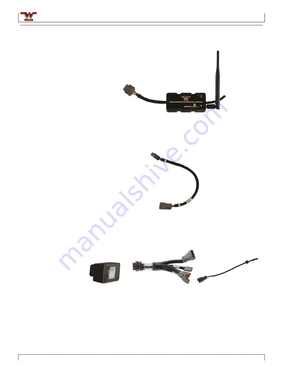
Figure 6. Electronic Control Unit (ECU)
Electronic control unit (ECU)
– Creates a local WiFi network signal that allows the
EFM system to communicate with an app running on an Android tablet in the
tractor cab. The Android app is provided free as a download.
Figure 7. ECU to Product Node Extension Cable
ECU to Node Extension cable
– Connects the ECU to the first product node in a
chain of multiple product nodes
Figure 8. 4CH Node, 4CH Node Harness and Single-Sensor Cable
4-channel (4CH) node, 4CH node harness and single sensor cable
– The 4CH node
brings together signals from up to four flow sensors and sends the signal to the ECU.
A 4CH harness connects the node to four single-sensor cables. Each 4CH node has
six connectors: four 3-pin female Deutsch connectors (for sensor cables), one 8-pin
female Deutsch connector (for connecting to the next node in the chain, or to a
terminator), and one 8-pin male Deutsch connector (for connecting to the previous
node in the chain, or the ECU)


