White Rodgers 1F98EZ-1621 Скачать руководство пользователя страница 7

7

W/E

W2

Y

Y2

G

O/B

HM

DHM

"  

 "  J& %
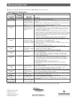
indicate the selections of the Comfort Interface. The following 
tables show the LED indications if LED indications are turned on. 
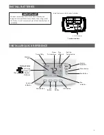
Remove Equipment Control Module cover and press the LED switch 
" %J&$  #J&1

Conventional Pump

Gas or Elect

Gas or Elect

Amber

Amber

W/E

Amber

Amber

W

2

Amber

Green

Y

Amber

Green

Y

2

Amber

Green

G

Amber

Green

O/B

RH

DRY

Green

Amber

HM

RH

DRY

Green

Amber

DHM

= Amber

= Green

01

K01

LED Indicator legend:

J&X%# %
J&X%>   "

 W/E 

– 

1

st Stage Heating or Auxiliary 

  W

2

 – 

2

nd Stage Heating or Auxiliary

 Y 

– 

1

st Stage Cooling

  Y

2

 – 

2

nd Stage Cooling

  G – Fan

 !Z

 &!Z&

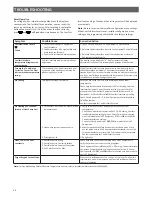
CHECK SYSTEM OPERATION

NOTE

        "
$             
$$     <@3
      Z

Apply power to Equipment Control Module.

Fan Operation

If your system does not have a 

G

 terminal connection, skip to 

< (

section.

1.

   Press 

FAN

 button. Blower should turn on.

2. 

 Press 

FAN

 button. The blower should stop immediately.

3.

  “

” indicates fan is in auto mode.

< (

1.

   Press 

Heat

 or 

A/C

 button to heat or cool. Run temperature 

1

above or below room temperature. The heating or cooling  

system should start.

2.

  For staging systems, run temperature 

3

o

 above or below room 

temperature. Heat or Cool - LED display will be indicated on 
equipment control.

3.

   Run temperature to below or above room temperature. The 

 1

<!- &

1.

 < !< !-  


+     
 % !

#7

 and 

8

.

( (  -


Your Comfort Interface is designed to determine the optimum 
time to activate the second stage. Simply raising the temperature 
in heating or lowering it in cooling will not always force the 
Comfort Interface to bring the second stage on quickly. There is a 
  @6\@      
   

EXAMPLE: For the last 2 hours the Comfort Interface is set on 

70

o


and the room temperature is 

70

o

 with the equipment using only the 

      ^      
within 

1

o


of setpoint, the Comfort Interface will delay the second 

stage for a longer time if you manually raise the temperature or 
if the room temperature quickly changes. Once the second stage 
 %    _   1  
# %              +     1
       %        #  
making temperature the second stage will delay longer. When 
             ^ 
temperature in a reasonable time, the second stage will come on 
sooner. This built in function automatically optimizes the use of 
additional stages of heat or cool. 

Содержание 1F98EZ-1621

Страница 1: ...INSTRUCTIONS CAREFULLY BEFORE INSTALLING OR OPERATINGTHIS CONTROL COULD CAUSE PERSONAL INJURYAND OR PROPERTY DAMAGE INSTALLATION INSTRUCTIONS EquipmentControl Module Comfort Interface Remote Sensor ou...

Страница 2: ...ctric Heat Only Cool Only or Heat Cool Systems 2 2 Heat Pump Single orTwo Compressor Systems with up to 2 Stages of Aux Em Heat 4 2 Heat Pump with Dual Fuel Single orTwo Compressor Systems with up to...

Страница 3: ...in place Do not drill into critical furnace components Wall anchors and screws are provided for dry wall mounting 3 16 See next page for wiring 5 1 Remove the cover from the Equipment Control Module...

Страница 4: ...HM Switch DHM Switch Outdoor Condenser A C or Heat Pump Y Y2 O B C if Heat Pump DHM DHM2 HM2 W E W2 Y Y2 G O B L HM Indoor Air Handler Furnace Connections Heat Stage 1 Indoor Unit or Furnace Conventi...

Страница 5: ...BATTERIES INSTALLER QUICK REFERENCE Install batteries in the Comfort Interface Room Temperature Time of Day System Indicator Heat Button A C Button Setting Temperature Day ofWeek Fan Indicator Run Bu...

Страница 6: ...10 0 1 On OFF 01 345 past 80 01 Selecting On energizes the DHM terminal s and fan terminal G when humidity is above the 6 from the heating and cooling system Note 7 Menu 8 11 0 1 ID Hum On OFF On 9 se...

Страница 7: ...emperature 1o above or below room temperature The heating or cooling system should start 2 For staging systems run temperature 3o above or below room temperature Heat or Cool LED display will be indic...

Страница 8: ...g two mounting screws J 1 Interface operation 6 Comfort Interface can be attached after checking operation LOCATEAND MOUNTCOMFORT INTERFACE 55 4 IMPORTANT 9 0 1 Wireless Devices see 1 Sub base Comfort...

Страница 9: ...nt Control Module Required Remote Sensor 1 if installed Remote Sensor 2 if installed Outdoor Remote Sensor if installed Remote Sensor 3 if installed Return Air Sensor required 4 Press the Run button t...

Страница 10: ...Interface Equipment Control Module is calling for cool Check for broken or shorted wire from Equipment Control Module to HVAC Equipment If LED is OFF or solid ON Comfort Interface not calling Check 2...

Страница 11: ...delete 4 Press and hold the and buttons simultaneously to delete each device Press until the display shows the next device to delete 5 PresstheRun buttontoexitthemenu 3 5 1 Power the device 2 Go to a...

Страница 12: ...demand signal is intermittent 2 Time delay or control board defective 3 If high pressure switch present go to Flash Code 2 information 4 If low pressure switch present go to Flash Code 1 information...

Отзывы: