


6
9
3 '
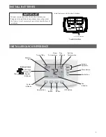
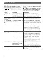
On the Home Screen Display, press and hold the
Menu
button for approximately
5
seconds to enter the Comfort Interface Options
! $
Menu
button again for approximately
5
"
Menu. Press
%
#
Menu
4
Number
SS
1
MS
2
HP
1
HP
2
-
0;- 1
Press
or
to select options
Description
01
MS
2
SS
1
#<)
2
#<)
1
MS
2
= Multi-Stage conventional (no heat pump)
HP
1
= Single compressor
HP
2
= 2 compressor 2 speed compressor
SS
1
= Single Stage conventional (no heat pump)
02
0=3(1
ELE
Gas setting: Furnace controls blower
Elec setting: Comfort Interface controls blower
0>1
GAS
03
0&1
On
B
“O” Energizes O/B reversing valve terminal in cooling
“B” Energizes O/B reversing valve terminal in heating
04
< 3!&?
< 3!3&?#
< ;&?#
< &?#3!&?
%
1
or MS
2
3%< 3!&?
3%< 3!3&?#
3%< ;&?#
3%< &?#3!&?
%$
1
or HP
2
05
0'1
CR Heat
;3#(>
2
1. If longer cycles are desired, set to SL.
Heat cycle rate: Fast, Med, and Slow
06
0'1
CR A/C
;3#(>
2
1
Cool cycle rate: Fast, Med, and Slow
07
0'1
CR Heat A/C
;3#(>
1
2)
Heat Pump cycle rate: Fast, Med, and Slow
08
0;31
43%<
SL
!
1
2
)
Auxiliary cycle rate: Fast, Med, and Slow
09
0&?1
CA
On
""#$
&
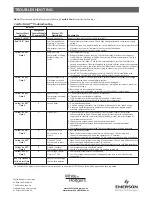
Enables active protection for the compressor. If the CA module sends alerts for condition
number
#2, 3, 4, 6
or
7
the interface will cancel the call for cool to protect compressor. The
interface will blink setpoint and display “Call for Service” as well as the Comfort Alert numbers.
(see troubleshooting for Comfort Alert)
&;;
Will disable the active protection for the compressor
10
0&?1
- <
On
%&
& # ' *
OFF
' + 01 345
past
80%
01
Selecting
On
energizes the DHM terminal(s) and fan terminal (G) when humidity is above the
6 +
from the heating and cooling system.
Note:
7" & " ' %
Menu #
8
)
11
0&?1
ID Hum
On
%
# ' *
OFF
' *
On
9 ! '* ';*% # %
setting. This feature is often used on steam systems and is independent from the call for heat or cool.
Note:
7" " ' %
Menu #
7
)
12
0&?1
CL
On
'(
>&
Will cause the interface to wait 5 minutes between cooling cycles. This is intended to help
protect the compressor from short cycling. Some newer compressors already have a time delay
built in and do not require this feature. Your compressor manufacturer can tell you if the lockout
feature is already present in their system. When the Comfort Interface compressor time delay
%> "
>&;;
Will disable the feature
13
0&?1
CO
On
"*
CO
ON
6" 1
When compressor turns on (for a call for heat in heat pump or a call for cool) the fan will be
" # % #
1 % ?@
additional cooling from the system.
&&;;
There will be no delay in fan operation
14
MS
2
0&1
FA Heat
&?
+
ON
- Will enable this feature if you need to rapidly heat your home. Manually changing the
setpoint by
3
degrees or more will enable all stages of heat.
OFF
- May not bring on secondary rapidly because it allows the Comfort Interface to compute
the optimum time to stage.
15
MS
2
0&1
FA A/C
&?
+
&
Will enable this feature if you need to rapidly cool your home. Manually changing the
setpoint by
3
degrees or more will enable all stages of cool.
&;;
May not bring on secondary rapidly because it allows the Comfort Interface to compute
the optimum time to stage.
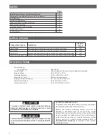
CONFIGURE COMFORT INTERFACE FOR SYSTEM


