


2
WARNING
!
ATTENTION: MERCURY NOTICE
This product does not contain mercury. However, this product
may replace a product that contains mercury.
Mercury and products containing mercury must not be
discarded in household trash. Do not touch any spilled
mercury. Wearing non-absorbent gloves, clean up any spilled
mercury and place in a sealed container. For proper disposal of
a product containing mercury or a sealed container of spilled
mercury, place it in a suitable shipping container. Refer to
for location to send product
containing mercury.
CAUTION
!
! " #
$ $%
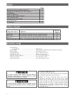
APPLICATIONS
INDEX
&
Applications
'%
(
Single Stage
Gas, Oil, Electric, Heat Only, Cool Only or Heat Cool Systems
1/1
Multi-Stage
Gas, Oil, Electric, Heat Only, Cool Only or Heat Cool Systems
2/2
Heat Pump
Single or Two Compressor Systems with up to 2 Stages of Aux / Em Heat
4/2
Heat Pump with Dual Fuel Single or Two Compressor Systems with up to 2 Stages of Fossil fuel Heat
4/2
SPECIFICATIONS
Electrical Rating:
Input-Hardwire
.......................................................
20
to
30
VAC
Terminal Load ................................................................
1.0
A per terminal,
2.5
A maximum all terminals combined
Setpoint Range ..............................................................
45° to 99°F (7° to 37°C)
Operating Ambient ........................................................
32°F to +105°F (0° to +41°C)
Operating Humidity .......................................................
90%
non-condensing max.
Shipping Temperature Range .........................................
-40° to +150°F (-40° to +65°C)
Dimensions Interface .....................................................
4-1/2”H x 6”W x 1-1/4”D
Dimensions Control .......................................................
5-1/2”H x 5-3/4”W x 1-1/2”D
)
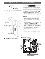
Mount Return Air Sensor and Equipment Control
3
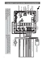
Equipment Control Module Wiring to HVAC Equipment
4
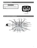
Install Batteries
5
Installer Quick Reference
5
6
Check System Operation
7
Locate and Mount Comfort Interface
8
View Wireless Devices
8
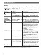
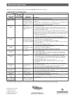
Troubleshooting
10


