


www.white-rodgers.com
www.emersonclimate.com
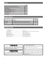
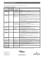
PART NO.
37-7235A
1114
Provides Wireless Control for up to
4
Heat/
2
Cool Heat Pump Stages
or up to
2
Heat/
2
Cool Stages on Conventional Systems
1F98EZ-1621
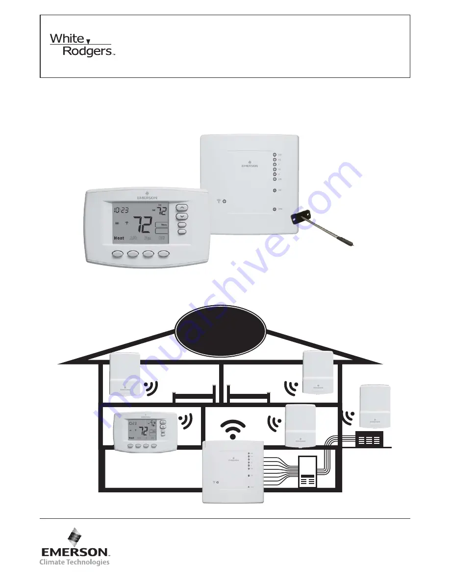
Emerson® Blue™ Wireless Easy Install™
FAILURE TO READ AND FOLLOW ALL INSTRUCTIONS CAREFULLY
BEFORE INSTALLING OR OPERATING THIS CONTROL COULD CAUSE
PERSONAL INJURY AND/OR PROPERTY DAMAGE.
INSTALLATION INSTRUCTIONS
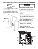
Equipment Control
Module
Comfort Interface
Remote Sensor
(outdoor location)
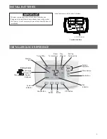
Model
1F98EZ-1641
Includes Comfort/User Interface, Equipment Control
and one Wireless Remote Sensor
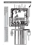
Comfort Interface
Equipment Control
Module
Return Air Sensor
(RAS)
1F98EZ-1621
will accept
up to
3
remote sensors
1
Optional Remote
Sensor(s) not included
[
[


