background image

23015-9-1108

Page 9

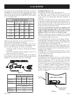
Figure 5

The gas pipeline can be brought in through the right or left side of 

the appliance. The insert has a Flexline with shutoff valve located 

on the right side when facing the unit. 

See Figures 5 and 6.

  Consult 

the current National Fuel Gas Code, ANSI Z223.1 CAN/CGA-B149 

(.1 or .2) installation code.

Installing the Main Gas Cock

Each appliance should have its own manual gas cock.

A manual main gas cock should be located in the vicinity of the 

unit. Where none exists, or where its size or location is not ad-

equate, contact your local authorized installer for installation or 

relocation.

Compounds used on threaded joints of gas piping shall be resistant 

to the action of liquefied petroleum gases. The gas lines must be 

checked for leaks by the installer. This should be done with a soap 

solution watching for bubbles on all exposed connections, and if 

unexposed, a pressure test should be made. 

never use an exposed flame to check for leaks. Appliance must 

be disconnected from piping at inlet of control valve and pipe 

capped or plugged for pressure test. Never pressure test with 

appliance connected; control valve will sustain damage!

NOTE: 

The millivolt gas controls are equipped with a captured 

screw type pressure test point, therefore it is not necessary to provide 

a 1/8" test point up stream of the control.

When using copper or flex connector use only approved fittings. 

The appliance and it’s individual shut off valve must be disconnected 

from supply piping system during any pressure testing of that system 

at test pressures in excess of 1/2 psig (3.5kPa).

The appliance must be isolated from the gas supply piping system 

by closing its individual manual shut off valve during any pressure 

testing of the gas supply piping system at test pressures equal to or 

less than 1/2 psig (3.5kPa).

Attention!

 If one of the procedures results in pressures in excess 

of 1/2 psig (14" w.c.) (3.5 kPa) on the fireplace gas valve, it will 

result in a hazardous condition.

Checking Manifold pressures

Both  Propane  and  Natural  gas  valves  have  a  built-in  pressure 

regulator in the gas valve. Natural gas models will have a manifold 

pressure of approximately 3.5" w.c. (.871kPa) at the valve outlet 

with the inlet pressure to the valve from a minimum of 4.5" w.c. 

(1.120kPa) for the purpose of input adjustment to a maximum of 

14.0" w.c. (3.484kPa). Propane gas models will have a manifold 

pressure approximately 10.0" w.c. (2.49kPa) at the valve outlet 

with the inlet pressure to the valve from a minimum of 10.8" w.c. 

(2.68kPa) for the purpose of input adjustment to a maximum of 

14.0" w.c. (3.484kPa).  

Gas Supply pressure (inches w.c.)

Minimum Normal

Maximum

Natural Gas

4.5"

7.0"

14.0"

LP (Propane)

10.8"

11.0"

14.0"

Manifold Pressure (inches w.c.)

Normal (HI)

Natural Gas

3.5"

LP (Propane)

10.0"

Note:

 Never use plastic pipe. Check to confirm whether your 

local codes allow copper tubing or galvanized.

Note:

 Since some municipalities have additional local codes, it is 

always best to consult your local authority and installation code.
The use of the following gas connectors is recommended:
—  ANS Z21.24 Appliance Connectors of Corrugated Metal Tubing 

and Fittings.

—  ANS  Z21.45 Assembled  Flexible Appliance  Connectors  of 

Other Than All-Metal Construction

The above connectors may be used if acceptable by the authority 

having jurisdiction. The state of Massachusetts requires that a flexible 

appliance connector cannot exceed three feet in length.

Recommended Gas pipe Diameter

pipe Length

Schedule 40 pipe 

Inside Diameter

Tubing, Type L

Outside Diameter

Nat.

L.P.

Nat.

L.P.

0-10ft

0-3m

1/2"

12.7mm

3/8"

9.5mm

1/2"

12.7mm

3/8"

9.5mm

11-40ft

4-12m

1/2"

12.7mm

1/2"

12.7mm

5/8"

15.9mm

1/2"

12.7mm

41-100ft

13-30m

1/2"

12.7mm

1/2"

12.7mm

3/4"

19mm

1/2"

12.7mm

101-150ft

31-46m

3/4"

19mm

1/2"

12.7mm

7/8"

22.2mm

3/4"

1.9 mm

GAS SUppLY

GAS FLEX LINE WITH

SHUTOFF VALVE

(PROVIDED)

FRONT OF

INSERT

RIGHT SIDE OF INSERT

Figure 6

Содержание Dv25IN33L-1

Страница 1: ...ce is not convertible for use with other gases unless a certified kit is used GAS FIRED Installer Leave this manual with the appli ance Consumer Retain this manual for future refer ence Do not store or use gasoline or other flamma ble vapors and liquids in the vicinity of this or any other appliance WHAT TO DO IF YOU SMELL GAS Do not try to light any appliance Do not touch any electrical switch do...

Страница 2: ... 10 12 Vertical Termination 13 Alternate ON OFF Switch Installation 14 Surround Panel Installation 15 Blower Accessory Information 16 Log Placement 17 Operating Instructions 18 Standing Pilot Lighting Instructions 19 Standing Pilot Wiring 20 Standing Pilot Troubleshooting 21 Insert Maintenance and Service 22 Decorative Accessories 23 Insert Parts View 24 Insert Parts List 25 How to Order Repair Pa...

Страница 3: ...t clean Vent cap is hot while fireplace is in operation Installation and repair should be done by a qualified service person The appliance should be inspected before use and at least annually by a qualified service person More frequent cleaning may be required due to excessive lint from carpeting bedding materials etc It is imperative that control compartments burners and circulating air passagewa...

Страница 4: ... perform service or make adjustments in an area where the conditions are such that you may not detect the odor if there has been a leak of LP Gas Odor fade due to oxidation by rust or adsorption on walls of new cylinders and tanks is possible Therefore people should be particularly alert and careful when new tanks or cylinders are placed in service Odor fade can occur in new tanks or reinstalled o...

Страница 5: ...having jurisdiction State of Massachusetts The installation must be made by a licensed plumber or gas fitter in the Commonwealth of Massachusetts The installation must conform with local codes or in the absence of local codes with the National Fuel Gas Code ANSI Z223 1 NFPA 54 Natural Gas and Propane Installation Code or CSA B149 1 in Canada Available from the American National Standards Institute...

Страница 6: ...ing to an existing round fireplace chimney pipe DVVK3FV Vertical Vent Kit 25 Two pieces of 25 FlexVent Rectangle Cap Flashing connectors and clamps Recommended when installing to a square or rectangular clay flue DVK35 Vent Extension Kit 35 flex vent extension section with 2 connectors and 4 clamps Note When installing vent caps special locally made flashings may be required to properly seal the v...

Страница 7: ...4 28 14 1 2 11 1 8 25 1 4 12 3 4 17 18 5 16 27 6 3 4 9 20 25 5 8 40 DV33IN 22 3 4 31 16 14 1 8 28 1 4 14 1 4 18 3 4 21 5 16 30 8 1 4 10 1 2 21 1 2 28 5 8 43 DV35IN 24 3 4 34 16 16 1 8 31 1 4 14 1 4 21 3 4 23 5 16 33 8 1 4 10 1 2 23 30 5 8 46 A D C B Figure 2 Fireplace Opening Dimensional Information Sizing MINIMUM FIREPLACE OPENING DIMENSIONS MODEL NO HEIGHT A FRONT WIDTH B DEPTH C REAR WIDTH D DV...

Страница 8: ...0 1 3 4 23 11 Combustible Material No greeting cards stockings or ornamentation of any type should be placed on or attached to the fireplace The flow of heat can ignite combustibles Figure 4 8 MINIMUM CLEARANCE TO PERPENDICULAR COMBUSTIBLE SIDE WALL FROM EDGE OF DOOR FRAME Figure 3 ...

Страница 9: ...ures results in pressures in excess of 1 2 psig 14 w c 3 5 kPa on the fireplace gas valve it will result in a hazardous condition Checking Manifold Pressures Both Propane and Natural gas valves have a built in pressure regulator in the gas valve Natural gas models will have a manifold pressure of approximately 3 5 w c 871kPa at the valve outlet with the inlet pressure to the valve from a minimum o...

Страница 10: ...isting air circulation vents or grills NOTE Cutting of sheet metal parts of a fireplace in order to install the fireplace insert is prohibited WARNING Only the surround as supplied may be used to cover integral grills on the solid fuel burning fireplace No other components such as shrouds sheet metal plates etc may be used to seal off vents 7 To assure top performance safety and efficiency inserts...

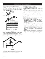
Страница 11: ...himney may need to be removed to allow installation of the flexible vent pipe When installing into a zero clearance factory built wood burning fireplaces the use of the DVKI Round Vertical Termination Kit should allow you to mount the vent adaptor and cap to the exposed round chimney pipe easily Connecting the Vent Pipe Caution Sharp edges Always use gloves when installing Install the 3 inch flexi...

Страница 12: ...ENT CONNECTION RETAINER SCREWS MAY BE INSTALLED THROUGH THE VENT CLAMPS TO ENSURE POSITIVE SECUREMENT OF VENTING SCREWS ADDED THROUGH VENT CLAMPS TO RETAIN VENTING TO COLLARS RECOMMENDED USE HIGH TEMP SEALANT ON VENT CONNECTIONS USE HIGH TEMP SEALANT ON VENT CONNECTIONS ROUND TERMINATION CAP DVKI KIT ROUND CO LINEAR TO CO AXIAL ADAPTOR BLOWER ACCESS COVER PLATE BLOWER POWER CORD OPTIONAL LOW VOLTA...

Страница 13: ...ently dripping out at joints or seams Condensate can cause corrosion of caps pipe and fittings It may be caused by having excessive lateral runs or having exterior portions of the system exposed to cold weather 4 Inspectjointstoverifythatnopipesectionsorfittingshavebeen disturbed and consequently loosened Also check mechanical supports such as wall straps or plumbers tape for rigidity Determining ...

Страница 14: ...d panel assembly against the face of the insert and align the lower retaining tabs with the notches on the insert sides Lift the surround panel assembly slightly until the bottom return flange top panel is positioned over the top flange on the insert This secures the sur round panel assembly to the insert without screws Traditional Cast Iron Surrounds 1 Find the coiled low voltage wire assembly an...

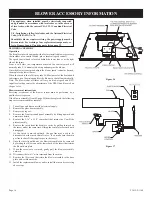
Страница 15: ...N FINISHING THE FIREPLACE INSERT NEVER OBSTRUCT OR MODIFY THE AIR INLET OUTLET LOUVERS ON THE FIREPLACE IN SERT IN ANY MANNER NOTE INSTALL SURROUND PANELS SO THAT THE TOP PANEL RETURN FLANGE SLIDE S OVER THE TOP FLANGE ON THE INSERT 1 Ref SURROUND PANEL ASSEMBLY ENGAGE SIDE PANEL HOOKS WITH THE NOTCHES PROVIDED ON THE SIDE FLANGES Figure 14 Figure 15 ...

Страница 16: ...and BTU input level setting control by adjustment of the HI LO knob located on the gas valve Blower removal instructions Servicing or removal of the blower system must be performed by a qualified service person If the blower assembly Item 45 page 24 must be replaced the following steps are recommended for removal 1 Turn off gas and disconnect the electrical supply 2 Remove the glass door assembly ...

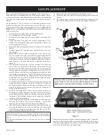
Страница 17: ... support Note DV25IN models incorporate two small tabs in the rear log support that keep the back log positioned correctly DV33IN models have one small tab in the rear log support to ensure the back log is in the correct position The DV35IN models will have two tabs bent forward in the rear log support to ensure proper left to right positioning of the log plus one small tab near the center that ke...

Страница 18: ...N position This time period allows the millivolts electrical current to build up to a sufficient level allowing the gas control to operate properly 1 Follow the SAFETY and LIGHTING INSTRUCTIONS for standing pilot controls found in this manual and on labels found in control compartment behind the door assembly CAUTION Duringtheinitialpurgingandsubsequentlightings never allow the gas valve control k...

Страница 19: ...ch to desired setting FOR YOUR SAFETY READ BEFORE LIGHTING Warning If you do not follow these instructions exactly a fire or explosion may result causing property damage personal injury or loss of life A This appliance has a pilot which must be lighted by hand When lighting the pilot follow these instructions exactly B Before lighting smell all around the appliance area for gas Be sure to smell ne...

Страница 20: ...ptional Wall Switch Position the wall switch in the desired position on a wall Run a maximum of 25 feet 7 8m or less length of 18 A W G minimum wire and connect it to the fireplace valve pigtails WARNING DO NOT CONNECT THE 110 120 VAC TO THE WALL SWITCH OR THE CONTROL VALVE WILL BE DESTROYED CAUTION LABEL ALL WIRES PRIOR TO DISCONNEC TION WHEN SERVICING CONTROL WIRING ERRORS CAN CAUSE IMPROPER AND...

Страница 21: ...ctions from the thermopile at the gas valve terminals are tight and the thermopile is fully inserted into the pilot bracket Check the thermopile with a millivolt meter Take the reading atTH TP TPterminals of the gas valve The meter shouldread350millivoltsminimum whileholdingthevalve knob depressed in the pilot position with the pilot lit and the REMOTE OFF ON switch in the OFF position Replace the...

Страница 22: ...sure that no debris is interfering with the flow of air Inspect entire vent system for proper function Cleaning Logs Use a soft brush attachment on a vacuum cleaner to gently remove dust or soot deposits from logs and burner Cleaning Glass Door Frequency After the first 3 to 4 hours of use As necessary after initial cleaning By Home owner Task Remove and clean glass after the first 3 to 4 hours of...

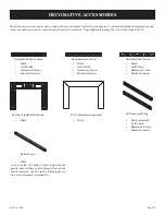
Страница 23: ...at your dealer can furnish contact Empire Comfort Systems Inc Nine Eighteen Freeburg Ave Belleville Illinois 62220 Black Gold Finish Hammered Pewter Brushed Stainless Black Gold Finish Hammered Pewter Brushed Stainless Black Gold Finish Hammered Pewter Brushed Stainless Black Black Black Standard Gold Finish Hammered Pewter Brushed Stainless Black Used to finish off bottom of insert and surround p...

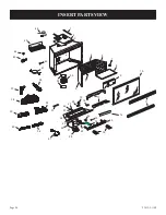
Страница 24: ...23015 9 1108 Page 24 INSERT PARTS VIEW 1 2 3 4 5 6 7 8 9 10 11 13 14 15 16 17 19 20 21 22 23 24 25 26 27 28 29 30 31 33 34 35 36 37 38 39 40 41 7 12 32 42 43 18 44 45 47 46 ...

Страница 25: ...T ASSEMBLY SIT LP 20 R9189 R9189 R9189 GASKET PILOT 21 R5676 R5676 R5676 AIR SHUTTER 22 P253 P253 P253 FITTING ORIFICE ANGLED 23a P286 P270 P244 ORIFICE MAIN BURNER NAT 23b P214 P250 P210 ORIFICE MAIN BURNER LP 24 23311 23017 23017 BURNER ASSEMBLY 25 22959 22959 22959 VALVE BRACKET 26 22739 22738 22738 TUBING ASSEMBLY 27 22973 22973 22973 SHIELD VALVE 28a R7577 R7577 R7577 VALVE SIT GAS NAT 28b R7...

Страница 26: ...ine the Part Number not the Index Number and the Description of each part from the following appropriate illustration and list Be sure to give all this information Fireplace Number Part Description Fireplace Serial Number Part Number Type of Gas Propane or Natural Do not order bolts screws washers or nuts They are standard hardware items and can be purchased at any local hardware store Shipments c...

Страница 27: ...23015 9 1108 Page 27 SERVICE NOTES ...

Страница 28: ...ms Empire Comfort Systems Inc 918 Freeburg Ave Belleville IL 62220 If you have a general question about our products please e mail us at info empirecomfort com If you have a service or repair question please contact your dealer www empirecomfort com ...

Отзывы: