background image

15627-5-0807

Page 6

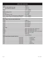
SPECIFICATIONS

Model

CIBV-30

Input BTU/HR (KW/H) Maximum

30,000 (8.7)

         BTU/HR (KW/H) Minimum

21,000 (6.2)

Height

27 3/4" (704mm)

Width

25 `/1" (647mm)

Depth including diverter

21" (533mm)

Gas Inlet

1/2" (13mm)

Size Draft Diverter Collar

4" (101mm)

Floor to top of collar on vertical position of Draft Diverter

27 3/8" (695mm)

Floor to center of collar on horizontal position of Draft 

Diverter

23 1/2" (596mm)

Stove Casting (Must be ordered with Firebox)

CIFB-1

Flat Black

CIPB-1

Porcelain Black

CIPG-1

Porcelain Green

CIPS-1

Porcelain Sand

CIPN-1

Porcelain Navy

CIPR-1

Porcelain Red

Accessories

TMV

Millivolt Wall Thermostat - Reed Switch

FRBC-1

Battery Operated Remote Control

FRBTC-1

Battery Operated Remote Control w/Thermostat

FREC-1

Electric Remote Control

FWS-1

Wall Switch

CIB-2

Automatic Blower

Stone Inlay Replaces Standard Grill Top

CII-2

Stone Inlay

Empress Green

CII-3

Stone Inlay

Hunan Jade

CII-4

Stone Inlay

Gray Botticino

CII-5

Stone Inlay

Azul

CII-6

Stone Inlay

Salome

CII-7

Stone Inlay

Black Swan

Содержание CIBV-30-20

Страница 1: ...structions are not followed exactly a fire or ex plosion may result causing property damage personal injury or loss of life Ne pas entreposer ni utiliser d essence ni d autres vapeurs ou liquides inflammables dans le voisnage de cet appareil ou de tout au tre appareil QUEFAIRESIVOUSSENTEZUNEODEUR DE GAZ Ne pas tenter d allumer d appareil Ne touchez a aucun interrupteur Ne pas vous servir des télépho...

Страница 2: ...Channel Installation 13 Log Placement 13 Operating Guidelines 14 Vent Safety Shutoff System 14 Venting 15 Lighting Instructions 16 Pilot Flame Characteristics 17 Main Burner Flame Characteristics 17 Wiring 18 19 Maintenance 19 20 Troubleshooting 21 How To Order Repair Parts 22 Parts List for CIBV 30 20 22 Parts View for CIBV 30 20 23 Parts List for Stove Casting 24 Parts View for Stove Casting 25 ...

Страница 3: ...res Voir les instructions d installation et d utilisation qui accompagnent l appareil DO keep the appliance area clear and free from combus tible material gasoline and other flammable vapors and liquids DOexamineburnersperiodically Cleanandreplacedam aged parts CAUTION The glass used in your heater is a special high temperature ceramic glass If the glass is cracked or damaged in any way it should b...

Страница 4: ...as pipes Theodorantinescapedgascanadsorborabsorbontoorintowalls masonry and other materials and fabrics in a room That will take some of the odorant out of the gas reducing its odor intensity LP Gas may stratify in a closed area and the odor intensity could vary at different levels Since it is heavier than air there may be more odor at lower levels Always be sensitive to the slightest gas odor If ...

Страница 5: ...h of Massachusetts The installation must conform with local codes or in the absence of local codes with the National Fuel Gas Code ANSI Z223 1 NFPA 54 Available from the American National Standards Institute Inc 11 West 42nd St New York N Y 10036 High Altitudes When installing this unit at an elevation above 2000 feet in the United States it may be necessary to decrease the input rating by changin...

Страница 6: ...tove Casting Must be ordered with Firebox CIFB 1 Flat Black CIPB 1 Porcelain Black CIPG 1 Porcelain Green CIPS 1 Porcelain Sand CIPN 1 Porcelain Navy CIPR 1 Porcelain Red Accessories TMV Millivolt Wall Thermostat Reed Switch FRBC 1 Battery Operated Remote Control FRBTC 1 Battery Operated Remote Control w Thermostat FREC 1 Electric Remote Control FWS 1 Wall Switch CIB 2 Automatic Blower Stone Inlay...

Страница 7: ...e connected control valve will sustain damage NOTE The gas control is equipped with a captured screw type pressure test point therefore it is not necessary to provide a 1 8 test point up stream of the control A gas valve and ground joint union should be installed in the gas line upstream of the gas control to aid in servicing It is required by the National Fuel Gas Code that a drip line be install...

Страница 8: ... Floor 0 inches Installation on Rugs and Tile If this appliance is to be installed directly on carpeting tile or other combustible material other than wood flooring the appli ance shall be installed on a metal or wood panel extending the full width and depth of the appliance The base referred to above does not mean the fire proof base as used on wood stoves The protection is primarily for rugs that ...

Страница 9: ... unit Detailed Instructions Follow 3 Refer to Figure 6 the leg pads will have the letter A and B stamped into the metal Place leg pad A and leg pad B at the bottom of each casting side Leg pad A attaches to the front of the casting side right and to the rear of the castingside left Legpad B attachestotherearofthecasting side right and to the front of the casting side left Position the 3 4 flange on...

Страница 10: ...en the casting back is attached to the casting sides 7 RefertoFigure7 therearcoverhas 4 keyholesforattachment to the casting sides Stand the casting sides on the floor with the 2 bolts attached half way into the edges of the rear cover positioned at the rear The large diameter holes in the keyholes of the rear cover will be toward the floor Working with one casting side at a time place the large dia...

Страница 11: ...ottom of the casting front Attach the bottom of the window to the casting front by inserting 1 3 8 bolt through retaining tab and into locator notch 10 Refer to Figure 8 attach the 4 1 1 4 x 1 2 retaining tabs to the casting front with 4 3 8 bolts The retaining tabs should be positioned downward from the casting front top to the casting front bottom 11 Refer to Figure 9 attach casting front to cas...

Страница 12: ...outs are 8 3 4 apart Position the angled front on the 12 12 The following procedure will provide a snug fit between the casting front and the casting sides Grasp the right front leg push inward on the leg in order to provide a snug fit between the casting front and the casting side Continue to hold the right frontlegasyoucompletelytightenthe 2 3 8 boltsthat attach the leg pad to the right casting si...

Страница 13: ...draft diverter Figure 12 Figure 13 1 Lower valve cover on firebox 2 Release two door latches at bottom of firebox 3 Grasp bottom of glass frame lift glass frame upward in order to release glass frame from lip on top of firebox 4 Remove logs from interior of firebox Remove all protective packaging from logs and interior of firebox 5 Place front log onto two 2 front pins on inner bottom 6 Place rear log ...

Страница 14: ...controlvalveallowsyoutoincreaseordecreasethe height of the main burner flame The control valve has a pressure regulator with a knob as shown in Figure 14 Rotate the knob clockwiseto HI toincreasetheflameheightandcounterclockwise to LO to decrease the flame height 3 When the heating season is over turn the on off switch to OFF and the control valve to OFF The system including the pilot light will be s...

Страница 15: ...filtration is normally adequate to provide for combustion and draft hood dilution Where appliances are installed in a confined space within a building thebuildingbeingofunusuallytightconstruction airfor combustionandventilationmustbeobtaineddirectlyfromoutdoors or from such spaces that freely communicate with the outdoors Under these conditions the confined space shall be provided with twopermanentop...

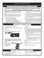
Страница 16: ...r to appliance if service is to be performed if applicable 3 Lower valve cover 4 Push in gas control knob slightly and turn clock wise to OFF Do not force 5 Raise valve cover TO TURN OFF GAS TO APPLIANCE LIGHTING INSTRUCTIONS 1 STOP Read the safety information above 2 Set the thermostat to lowest setting 3 Turn off all electric power to the appliance if appli cable 4 Lower valve cover 5 Push in ga...

Страница 17: ...urner Warning Turn off heater and let cool before cleaning After use cleaning of the main burner may be required for the proper flame The main burner may be cleaned by applying air pressure to the ports on the main burner Cleaning the Log Set and Firebox During the annual inspection and maintenance appointment the service person should clean dust lint and any light accumulation Correct Main Burner ...

Страница 18: ...structions in the FRBC 1 and FRBTC 1 to complete installation Note IfbatteriesfailinFRBC 1orFRBTC 1 andimmediateheat is desired turn the ON OFF REMOTE switch on wire channel from the REMOTE position to the ON position Electric 120 volt Operated Remote Control FREC 1 Connect the green and red stripped and bare wires on the ON OFF REMOTEswitchwireharnesstothewiresonremotereceiver that is a component...

Страница 19: ... that will obstruct the flow of combustion and ventilation air See clearances DO examine venting system periodically Clean and replace damaged parts Examinations should be made at the start of the heating season and also in mid heating season under average conditions Clean Burner and Control Compartment Keepthecontrolcompartment logs andburnerareassurrounding the logs clean by vacuuming or brushing...

Страница 20: ...o not use abrasive cleaners on glass Do not attempt to clean glass when glass is hot Failure to follow these warnings could cause a serious safety issue to the operator such as fire or other serious conditions Glass Assembly Replacement 1 Remove casting top from casting 2 Remove casting front from casting 3 Lower valve cover on firebox 4 Release two door latches at bottom of firebox 5 Grasp bottom of...

Страница 21: ...onnections from the thermopile at the gas valve terminals are tight and the thermopile is fully inserted into the pilot bracket Check the thermopile with a millivolt meter Take the reading at TH TP TP terminals of the gas valve The meter should read 325 millivolts minimum while holding the valve knob depressed the pilot position with the pilot lit and the ON OFF switch in the OFF position Replace ...

Страница 22: ...LD CAUSE INJURY OR DEATH Index Part No Number Description Index Part No Number Description 1 R 2708 PIEZO IGNITOR 2 15516 VALVE COVER ASSEMBLY 3 R 4053 LATCH 4 15490 VALVE BRACKET 5 R 3633 GAS VALVE NAT 5 R 3632 GAS VALVE LPG 6 R 2423 BRASS MALE CONNECTOR 7 15556 TUBING VALVE TO BURNER 8 P 253 ORIFICE FITTING 9 P 185 ORIFICE LPG 9 P 243 ORIFICE NAT 10 R 3357 SPRING 11 15569 AIR SHUTTER NAT 11 1555...

Страница 23: ...Page 23 15627 5 0807 PARTS VIEW FOR CIBV 30 20 ...

Страница 24: ...EEN ENAMEL 6 R 3707 TOP RED ENAMEL 6 R 3715 TOP NAVY ENAMEL 7 CI 007 RETAINING TAB 4 REQUIRED 8 R 3946 SIDE RIGHT BLACK PAINT 8 R 3685 SIDE RIGHT BLACK ENAMEL 8 R 3693 SIDE RIGHT SAND ENAMEL 8 R 3701 SIDE RIGHT GREEN ENAMEL 8 R 3709 SIDE RIGHT RED ENAMEL 8 R 3717 SIDE RIGHT NAVY ENAMEL 9 R 3947 FRONT BLACK PAINT 9 R 3687 FRONT BLACK ENAMEL 9 R 3695 FRONT SAND ENAMEL 9 R 3703 FRONT GREEN ENAMEL 9 R...

Страница 25: ...Page 25 15627 5 0807 Models CIFB 1 CIPB 1 CIPG 1 CIPS 1 CIPN 1 CIPR 1 PARTS VIEW FOR STOVE CASTING ...

Страница 26: ...ed in hardware package 7 Route wires from fan control and ON OFF REMOTE switch within wire channel 8 When facing the rear of the appliance align and insert fan control with bracket into 1 3 8 x 2 opening on the left side of the rear cover 9 Attach wire channel to rear cover by using 4 hex head screws removed in Step 4 Refer to Wire Channel Installation Page 13 10 InsertAUTO OFF ON switch into rect...

Страница 27: ...rical source is utilized This appliance is equipped with a three prong grounding plug for your protection against shock hazard and should be plugged directly into a properly grounded three prong receptacle Do not cut or remove the grounding prong from this plug For an ungrounded receptacle an adapter which has two prongs and a wire for grounding can be purchased plugged into the ungrounded recepta...

Страница 28: ...7 Empire Comfort Systems Inc Nine Eighteen Freeburg Ave Belleville Illinois 62222 0529 PH 1 800 851 3153 PH 1 618 233 7420 FAX 1 800 443 8648 FAX 1 618 233 7097 E MAIL info empirecomfort com WEB SITE www empirecomfort com ...

Отзывы: