


30
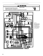
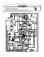
Wiring Diagram—WGGE4348, 60
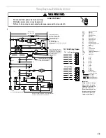
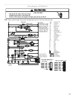
NOTE: Wiring is subject to change. Always refer to the wiring diagram on the unit for the most up-to-date wiring.
Goodman 6 Long
HIGH VOLTAGE!
WARNING
Disconnect ALL power before servicing.
Multiple power sources may be present.
Failure to do so may cause property damage, personal injury or death.
R
BU
W
G
Y
Y
W
Y
R
G
BU
R
R
BK
PR
BR
PR
BU
BK
R
PR
BK
PR
BK
Y
BU
PR
PR
Y
Y
R
R
R
PR
BR
BU
PR
BU
Y
PR
G
PR
Y
Y
BK
BK
BK
BK
Y
BU BU
R
R
OR
R
W
R
PR
R
BK
PR
R
R
R
BU
BU
BU
BU
OR
R
W
BR
BR
BK
PR
PR
BU
R
PR
Y
BU
BU
Y
W
BU
W
Y
G
R
Y
Y
W
W
R
F
C
H
Y
Y
BK
BK
BU
R
OR
To Thermostat
R
C
G
W
Speed-Up
Break F
or
Tw
o Stage Compressor
T2
C22
Mount
Scre
w
Required
T1
P2
Cool
P3
FU SE
3 A
MP
MAX
F1
1
P
135
N
O
C
E
120
150
1
1
8
2
1
9
7
0
1
4
2
5
6
3
1
I
D
1
L
S
F
Heat
Un
used
2
L
GND
Power Supply
208-230/1/60
Crankcase Heater Optional
Connected At L1, L2
Y1
Y/Y2
PLF
T1 T2 T3 T4 T5
CM
White Rodgers
Gas Control Valve
M V
GV
Honeywell
Gas Control Valve
(alternate)
M V
GV
PS
LS
ALS
L1
L2
C
T1
T2
C
COMP
S
R
VM
RS
C
IIC
RCCF
FS
IGN
3
2
1
4
5
6
1
C
24V
2
TR
3
240
3
4
2
1
VM R
L G N
208
EM
BU
BU
BU
Crankcase Heater
Optional
Use copper conductors only.
††Use NEC Class 2 wire.
For 208-volt transformer
operation, move black wire
from Terminal 3 to Terminal 2
on transformer.
L1 and L2 on
ICC control is
24V input.
Accessory economizer
plug (on select models)
adjacent to
blower housing
in return air
compartment
For different than factory speed tap,
change cooling speed at Motor T4 and
T5 terminals. Change heating speed at
Motor T2, T2 and T3 terminals.
Cooling Speed (Yellow Wire)
T4 Low Speed
T5 High Speed
Heating Speed (White Wire)
T1 Low Speed
T2 Medium Speed
T3 High Speed
Crankcase heater not
supplied on all units.
Y
PR
HPS
BU/PK
BU/PK