


2
TABLE OF CONTENTS
SAFETY INSTRUCTIONS...............................................................3
TO THE INSTALLER.......................................................................4
IMPORTANT NOTE TO THE OWNER REGARDING
PRODUCT WARRANTY .................................................................4
REPLACEMENT PARTS ................................................................4
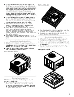
UNIT LOCATION.............................................................................4
Ground Level Installations Only ...................................................5
Rooftop Installations Only............................................................5
Roof Curb Installations Only ........................................................5
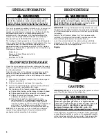
GENERAL INFORMATION.............................................................6
TRANSPORTATION DAMAGE ......................................................6
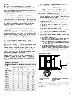
RIGGING DETAILS .........................................................................6
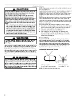
GAS PIPING ....................................................................................6
High Altitude Derate—U.S. Installations Only .............................7
Check Gas Piping ........................................................................8
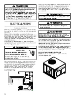
ELECTRICAL WIRING..................................................................10
Thermostat Location ..................................................................10
Unit Voltage ................................................................................11
Heat Anticipator Setting.............................................................11
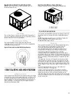
CIRCULATING AIR AND FILTERS..............................................11
Airflow Conversion .....................................................................11
Ductwork ....................................................................................11
Filters ..........................................................................................12
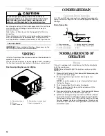
VENTING .......................................................................................12
CONDENSATE DRAIN .................................................................12
Condensate Drain Connection...................................................12
NORMAL SEQUENCES OF OPERATION...................................12
Heating .......................................................................................12
Cooling .......................................................................................13
Fan Only .....................................................................................13
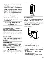
START-UP, ADJUSTMENTS, AND CHECKS.............................13
Heating Start-Up ........................................................................13
Pre-Operation Checks ...............................................................13
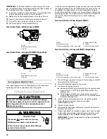
Gas Supply Pressure Measurement ..........................................14
Gas Manifold Pressure Measurement and Adjustment ............15
Gas Input Rate Check—Natural Gas Only ................................15
Main Burner Flame Check .........................................................16
Temperature Rise Check............................................................16
External Static Pressure Check .................................................16
Blower Speed Adjustments........................................................16
Limit Check.................................................................................16
UNIT SHUTDOWN ........................................................................17
COOLING START-UP...................................................................17
Compressor Protection Devices ................................................17
Cooling Refrigerant Charging.....................................................17
TROUBLESHOOTING ..................................................................17
Ignition Control Error Codes ......................................................17
Abnormal Operation—Heating...................................................17
Abnormal Operation—Cooling...................................................18
MAINTENANCE ............................................................................18
Filter Replacement or Cleaning..................................................18
Cabinet Finish Maintenance.......................................................18
Clean Outside Coil—Qualified Servicer Only.............................18
Condenser, Evaporator and Induced Drafter Motors ................18
Flame Sensor—Qualified Servicer Only.....................................19
Flue Passages—Qualified Servicer Only ...................................19
Cleaning Flue Passages—Qualified Servicer Only ....................19
Main Burner Flame—Qualified Servicer Only ............................19
Burner Flame ..............................................................................19
Cleaning Burners........................................................................19
ACCESSORIES AND FUNCTIONAL PARTS ..............................20
Sheet Metal Accessories............................................................20
Functional Parts..........................................................................20
General Information....................................................................20
APPENDIX .....................................................................................20
Blower Performance Data—Single Phase .................................20
Ignition Control Diagnostic Indicator Chart ...............................25
Heating Timing Chart .................................................................26
Cooling Timing Chart .................................................................26
Unit Dimensions .........................................................................27
Minimum Clearances..................................................................27
Wiring Diagram—WGGE4324, 30, 36, 42..................................28
Wiring Diagram—WGGE4324, 30, 36, 42..................................29
Wiring Diagram—WGGE4348, 60..............................................30
Wiring Diagram—WGGE4348, 60..............................................31
ASSISTANCE OR SERVICE .........................................................32