


28
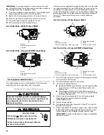
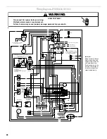
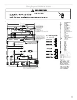
Wiring Diagram—WGGE4324, 30, 36, 42
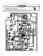
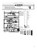
HIGH VOLTAGE!
WARNING
Disconnect ALL power before servicing.
Multiple power sources may be present.
Failure to do so may cause property damage, personal injury or death.
To THC
see THC Field Wiring Diagram
PR
OR
R
BU
Y
R
BK
BK
R
EC O N
PR
R
PR
IIC
GND
Power Supply
R
Y
BK
BK
T2
L2
CC
R
T1
L1
Crankcase Heater (optional)
208 to 230/1/60
BK
3
208
2
C
1
24 V
BU
TR A N S
240
GY
BK
PR
R
BU
BU
BU
BK
BU
BK
Y
PR
R C
S
COMP
BK
BK
PR
PR
R
R
LS
BK
BR
CM
BR
BR
EM
4 5
Y
1 2 3
Low
R
BU
Medium
EM
CAP. 2
BR
PR
BK
High
CAP 2
R
PR (L 2)
BK
BU
Y
R
FS
R
OR
R
H
C
F
Y
BR
CAP 1
BU
BK
PR
ALS
Y
Y
PS
PR
W
G
G
W
R
BU
Y
PR
R
C
Y/Y2 Y1
Y
BU
6
5
2
3
G
4
1
Y
PR
RS
MV
MV
GV
PR
BU
GV
PR
PR
BU
FS
IG N
VM
R
PR
Crankcase Heater (optional)
Connected at L1, L2
3 speed
optional
Alternate 3 speed motor
4 speed motor
For 208 volt transformer operation,
move the black wire from Terminal
3 to Terminal 2 on transformer.
For different than factory
speed tap, change cooling
speed at Cool Terminal (IIC)
and change heating speed
at Heat Terminal (IIC).
White-Rodgers
Gas Control Valve
Honeywell Gas
Control Valve
(alternate)
Accessory economizer plug
(on select models) adjacent
to blower
housing in
return air
compartment.
BK - High Speed
BU - Medium High Speed
Y (4-speed motor only) - Medium Low Speed
R - Low Speed
For different than factory speed tap, change cooling
speed at Cool Terminal (IIC) and change heating speed
at Heat Terminal (IIC).
BK - High Speed
BU - Medium High Speed
Y (4-speed motor only) - Medium Low Speed
R - Low Speed
For different than factory
speed tap, change cooling
speed at Cool Terminal (IIC)
and change heating speed
at Heat Terminal (IIC).
BK - High Speed
BU - Medium High Speed
Y (4-speed motor only) - Medium Low Speed
R - Low Speed
For different than factory
speed tap, change cooling
speed at Cool Terminal (IIC)
and change heating speed
at Heat Terminal (IIC).
BK - High Speed
BU - Medium High Speed
Y (4-speed motor only) - Medium Low Speed
R - Low Speed
PL
Wiring is subject to change.
Always refer to the wiring
diagram on the unit for the
most up-to-date wiring.
Replacement wire must be
the same size and type of
insulation as original (use
copper conductor only).
IMPORTANT:
Y
Y
Y
HPS
BU/PK
BU/PK