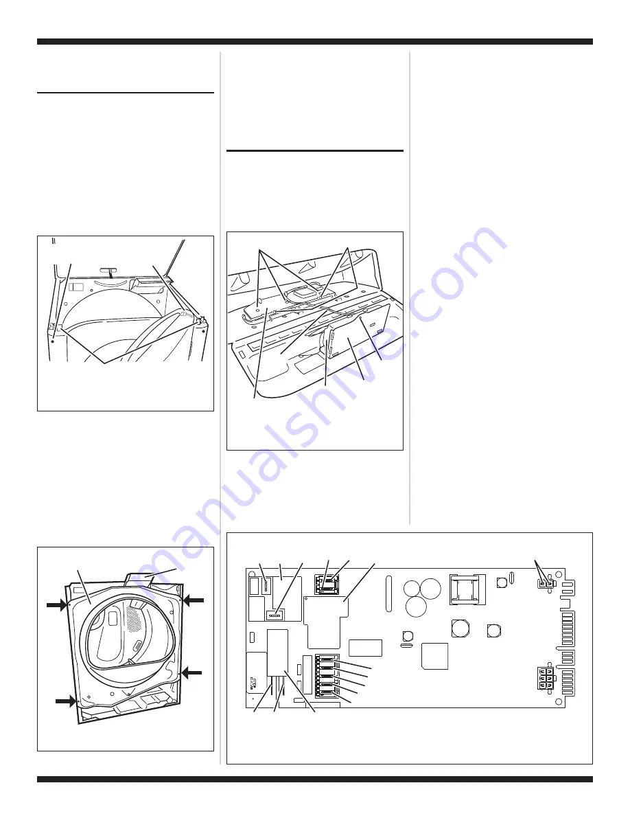
TECH SHEET - DO NOT DISCARD
PAGE 11
FOR SERVICE TECHNICIAN’S USE ONLY
PART NO. W10054150
4.
Press the Pause/Cancel button at any
time to cancel changes and exit from this
mode.
REMOVING THE FRONT
PANEL/DRUM ASSEMBLY
1.
Unplug dryer or disconnect power.
2.
Remove the lint screen.
3.
Remove the two screws holding the lint
screen duct to the top.
4.
Open the door.
5.
Push on the retaining clips located under
top of dryer on the right and left side
using a flat object such as a putty knife.
See figure 12.
6.
Slowly rotate top backwards and lean
against wall, or support with a prop rod.
7.
Disconnect the door switch wire harness
located on the right side. See figure 12.
8.
Remove the front panel/door assembly
by removing the two front cover screws at
the top of the panel inside the cabinet,
and lifting upward.
9.
Remove the front bulkhead by loosening
the upper two screws and removing the
lower two screws. See figure 13.
10.
Lower components can be accessed at
this time, however, if the drum is to be
removed, the belt must be removed. See
TEST #3, step 5, page 7.
Reinstalling the Front Panel/Drum
Assembly
Refer to preceding removal sections and
replace in reverse order
.
ACCESSING & REMOVING
THE ELECTRONIC
ASSEMBLIES
There are two electronic assemblies; the
machine control electronics and the user
interface electronics. See figures 14 and 15.
1.
Unplug dryer or disconnect power.
2.
Remove two screws from the rear of the
console assembly. Pull console towards
front of dryer to hinge open and/or
remove console.
Removing the Machine Control
Electronics
3.
Remove the wire connections to the
machine control assembly.
4.
Remove the one screw holding the
machine control assembly to the
metal bracket. See figure 14.
5.
Push in on the tab located on the back
of the machine control to slide it off
the bracket.
Removing the User Interface
Assembly
3.
Remove the wire connections from the
user interface assembly, including the
P5 ribbon cable. See figure 14.
4.
Remove the cycle selector knob from
the front of the console by firmly
pulling on it or carefully prying straight
upward.
5.
The user interface assembly is held to
the console insert panel by three
screws and two locking tabs. After the
screws are removed, lift each of the
locking tabs to remove the back cover
of the user interface assembly. See
figure 14.
6.
Remove the cycle selector switch from
the user interface assembly opening
by lifting the locking tab on the cycle
selector switch and turning the
selector switch in a counterclockwise
direction. See figure 16, page 12.
Door Switch
Wire Harness
Connector
Front Cover Screw
(Inside Cabinet)
Top Clips
Figure 12.
Slowly rotate top backwards
and support.
P9
1
5
1
P8
P14
P2
3
1
1
6
P4
1
1
8
3
P5
P3
1
P13
1
P/N XXXXXX Re
v X
Date Code
YDDD-xx
XXXX-XXX
MADE IN COO
N.O.
Black
COM
Red
Heater
Relay 1
Motor
Relay
Tan
Black-White
White
Green-Yellow
Brown
Blue
Black
Heater Relay 2
(Dual Element Model Only)
Yellow-Red
COM
Violet
N.O.
Black
Figure 15.
Machine control electronics.
Drum Face
Plate
Lint Screen
Duct
Figure 13.
Remove the front bulkhead.
Back Cover Locking Tabs
Metal Bracket
Machine Control
Electronics
Assembly
Screw
3 Screws
User Interface
Assembly Back Cover
P5
Ribbon
Cable
Figure 14.
Locate the electronic
assemblies.


