6
Orifice
7. Remove the caps from the suction and liquid pressure taps.
8. Remove the valve cores.
9. Connect an R-22 cylinder with clean refrigerant to the suction
pressure tap.
10. Connect the R-22 gauge set to the liquid line service valve
and connect a recovery machine with an empty recovery tank
to the gauge set.
11. Set the recovery machine for liquid recovery and start the
recovery machine in accordance with the manufacturer’s
instructions provided with the recovery system being used.
12. Open the gauge set valves to allow the recovery machine to
run until a vacuum level less than 0" Hg (gauge pressure) is
established in the existing system line set and indoor coil.
13. Invert the cylinder of clean R-22 and open its valve to allow
liquid refrigerant to flow into the system through the vapor
line valve.
14. After all of the liquid refrigerant has been recovered, switch
the recovery machine to vapor recovery to allow the recovery
machine to run until a vacuum level less than 0" Hg (gauge
pressure) is established in the existing system line set and
indoor coil in accordance with the manufacturer’s instructions
provided with the recovery system being used.
NOTE: A single system flush should remove all of the mineral oil
from the existing refrigerant lines and indoor coil. A second
flushing may be done (using clean refrigerant) if insufficient
amounts of mineral oil were removed during the first flush. A
second flushing may be required to ensure that the maximum
amount of oil is removed.
15. Close the valves on the inverted R-22 cylinder and gauge set.
16. Remove the recovery machine, gauges, R-22 cylinder and the
field provided fitting installed in Step 6.
17. Install the valve cores.
18. Install the R-410A thermal expansion valve specified for this
system in the indoor coil.
NOTE: R-410A systems use only thermal expansion valves.
19. Pressurize the lines and indoor coil with a pressure not to
exceed 20 psig.
20. Leak test the lines with a pressure not to exceed 20 psig.
21. Open the suction and liquid service valves fully.
22. Insulate the suction line with refrigerant line insulation
material of
¹⁄₄
" (6.4 mm) or more wall thickness.
23. Pack insulating material around refrigerant lines where they
penetrate the structure to protect the lines and to minimize
vibration transmission.
Connect Refrigerant Lines
Refrigerant lines must be connected by a licensed, EPA certified
refrigerant technician in accordance with established procedures.
IMPORTANT:
■
Connecting refrigerant lines must be clean, dehydrated,
refrigerant-grade copper lines. Heat pumps should be
installed only with specified line sizes for approved system
combination. See the Suction Line Sizes and Liquid Line
Sizes charts later in this section.
■
Avoid sharp bends or possible kinking in the refrigerant lines
during installation as this may cause a reduction in
performance.
■
To avoid contamination of the refrigerant system, do not
remove the caps from the lines or system connection points
until connections are ready to be completed.
Install Thermal Expansion Valve
W4GH8 heat pumps are designed for use with thermal expansion
valve systems only. An R-410A system will not operate properly
with an R-22 thermal expansion valve.
Thermal expansion valves equipped with Chatleff-type fittings are
available from the manufacturer. See Thermal Expansion Valve
Kits chart in “System Requirements.”
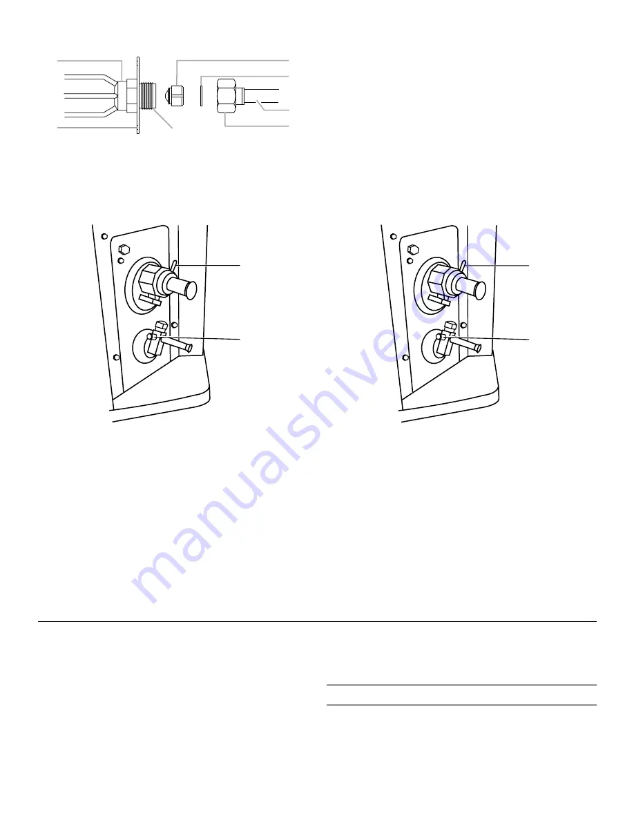
A. Distributor fitting
B. Piston orifice
C. Ring seal (supplied)
D. Orifice extension stub
E. 0.812" brass hex nut
F. Brass hex fitting
G. Mounting flange
A. Suction pressure tap
B. Liquid pressure tap
A
G
C
D
B
E
F
A
B
A. Suction pressure tap
B. Liquid pressure tap
A
B


